
Predictive method and apparatus for antenna selection in a wireless communication system

a wireless communication system and antenna selection technology, applied in the direction of diversity/multi-antenna systems, spatial transmit diversity, electromagnetic wave modulation, etc., can solve the problem that the preamble duration does not allow multiple antennas to be tested, and the signal quality is affected

Inactive Publication Date: 2005-07-07
AGERE SYST INC
View PDF9 Cites 173 Cited by
  • Summary
  • Abstract
  • Description
  • Claims
  • Application Information

AI Technical Summary

Benefits of technology

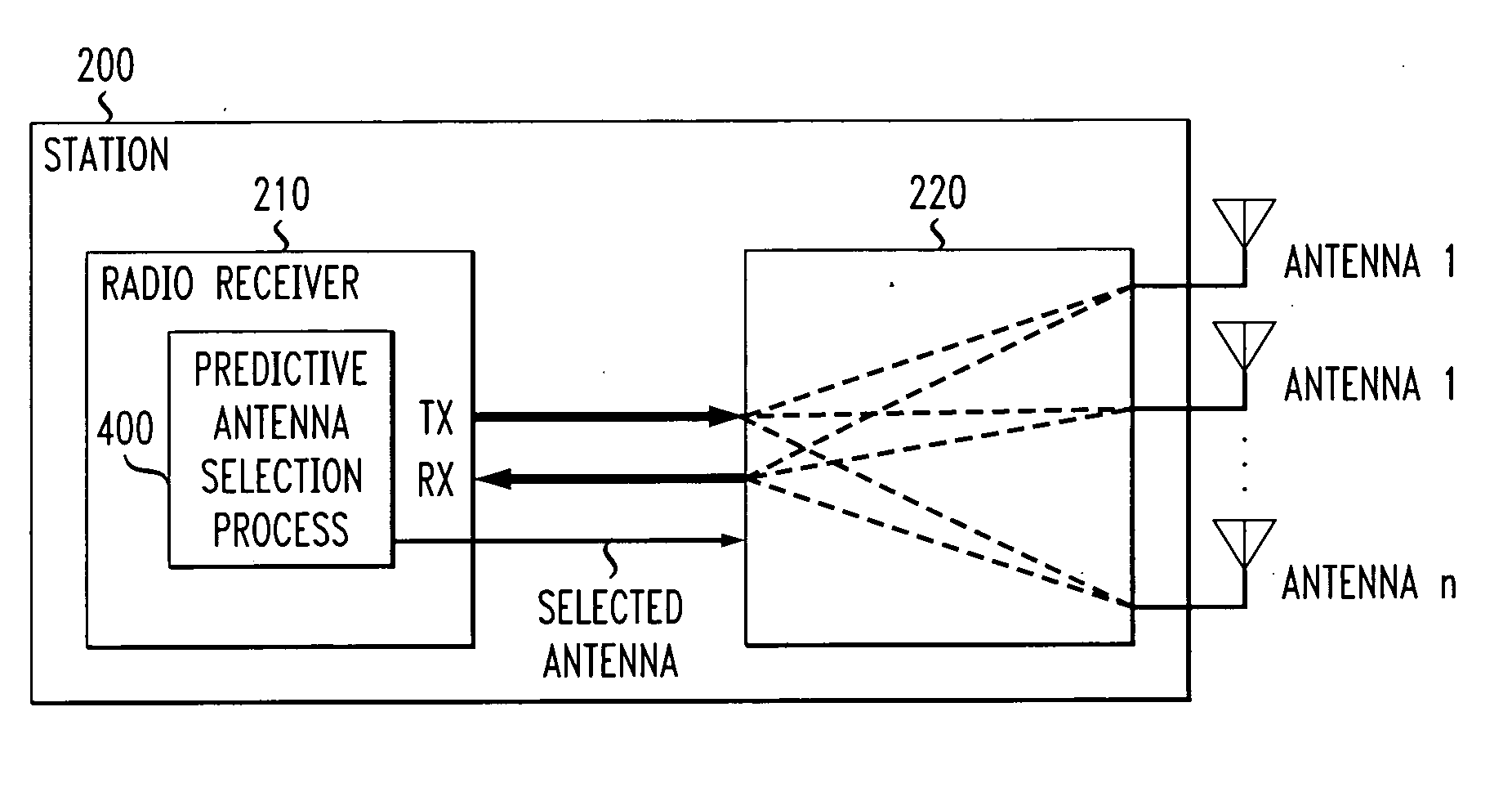
[0005] Generally, a predictive method and apparatus are disclosed for selecting an antenna to use in a multi-antenna wireless device. A predictive antenna selector predicts the best antenna (for both receiving and transmitting signals) based on the signal quality of the antenna for prior receiv

Problems solved by technology

In a wireless communication system, especially in an indoor environment, multipath fading is caused by reflections of the wireless signal interfering with each other at the receiver antenna, causing a degradation in the signal quality.
Thus, moving the antenna a small distance can make a significant difference in the signal quality.
The receiver generally cannot switch to a different antenna once the actual header or payload data is being received, because switching the antenna would cause data errors.
In many wireless implementations, however, the duration of the preamble does not allow multiple antennas to be tested, because the preamble is too short, or the time to perform a test on an antenna is too long.

Method used


Image

  • Predictive method and apparatus for antenna selection in a wireless communication system
  • Predictive method and apparatus for antenna selection in a wireless communication system
  • Predictive method and apparatus for antenna selection in a wireless communication system

Examples


Embodiment Construction

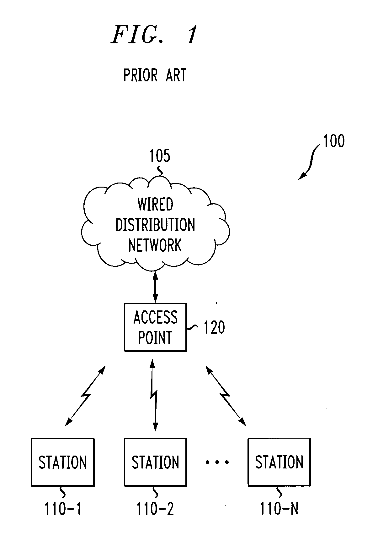
[0014]FIG. 1 illustrates a wireless network environment 100 in which the present invention can operate. The wireless network environment 100 may be, for example, a wireless LAN or a portion thereof. As shown in FIG. 1, a number of stations 200-1 through 200-N, collectively referred to as stations 200 and discussed below in conjunction with FIG. 2, communicate over one or more wireless channels in the wireless digital communication system 100. An access point 120 is typically connected to a wired distribution network 105 with other access points (not shown). The access point 120 typically provides control and security functions, in a known manner. In addition, the access point 120 acts as a central node through which all traffic is relayed so that the stations 200 can rely on the fact that transmissions will originate from the access point 120.

[0015] For example, in the IEEE 802.11 protocol, the access point 120 is the central node, and a station 200 or “client node” that is associa...


PUM


Abstract

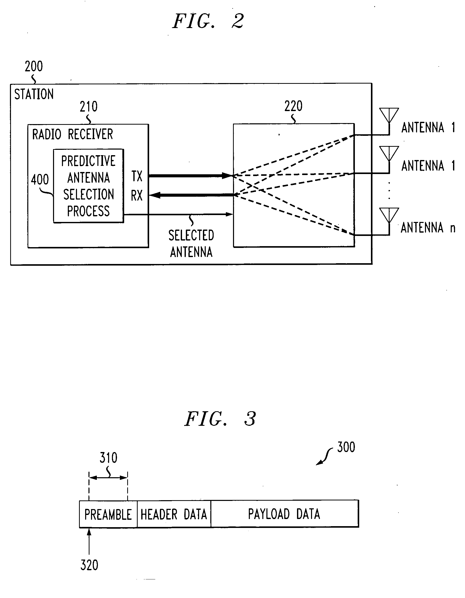
A predictive method and apparatus are disclosed for selecting an antenna to use in a multi-antenna wireless device. A predictive antenna selector predicts the best antenna (for both receiving and transmitting signals) based on the signal quality of the antenna for prior received frames. The quality of each antenna is evaluated, for example, in a random order, round robin fashion or according to some equal or weighted schedule. The signal quality can be evaluated for a given antenna during a preamble portion of a frame or for any frame up to an entire frame duration. A given antenna can be removed from the signal quality evaluation (for example, to a bad antenna list) if the given antenna fails to satisfy one or more predefined criteria, such as whether a signal quality of a given antenna is below a signal quality of a remainder of the plurality of antennas by a predefined amount. The signal quality of antennas on the bad antenna list can be reevaluated to determine when to return a removed antenna to the plurality of antennas that are evaluated.

Description

FIELD OF THE INVENTION [0001] The present invention relates generally to antenna diversity in wireless communication systems, and more particularly, to predictive techniques for selecting an antenna in such a wireless communication system. BACKGROUND OF THE INVENTION [0002] In a wireless communication system, especially in an indoor environment, multipath fading is caused by reflections of the wireless signal interfering with each other at the receiver antenna, causing a degradation in the signal quality. The reflections may be caused, for example, by various objects, such as walls, cabinets, doors or ceilings. These fading effects vary greatly with the position of the antenna. Thus, moving the antenna a small distance can make a significant difference in the signal quality. To overcome the problem of multipath fading, many wireless communications products employ antenna diversity techniques using two or more antennas. If one antenna has a poor signal quality due to a deep fade, the...

Claims


Application Information

Patent Timeline
IPC IPC(8): H04B7/06H04B7/08
CPCH04B7/0814H04B7/0608
Inventor HIDDINK, GERRIT WILLEM
Owner AGERE SYST INC
Learn More