
Electric vacuum cleaner

a vacuum cleaner and electric technology, applied in the direction of vacuum cleaners, cleaning filter means, domestic applications, etc., can solve the problems of dust deposited on the side of the longitudinal wall that cannot be sucked up, the performance of the motor fan cannot be achieved sufficiently, and the filter clogs, etc., to achieve the effect of less loss of air passag

Inactive Publication Date: 2005-07-14
TOSHIBA LIFESTYLE PROD & SERVICES CORP
View PDF11 Cites 5 Cited by
  • Summary
  • Abstract
  • Description
  • Claims
  • Application Information

AI Technical Summary

Benefits of technology

[0022] According to the structure mentioned above, since the dust sucked with the air goes straight by inertia and is collected, and the air is sucked by the motor fan through the opening, the air and the dust are separated without generating the spiral flow, therefore loss of air passage becomes less.

Problems solved by technology

Like so, because the direction of the air is changed twice, its loss of air passage is large, and furthermore, because the air is sucked to the motor fan 2 after revolving inside of the dust cup 1, its loss of air passage becomes exceedingly large, causing a problem that a performance of the motor fan cannot be achieved sufficiently.
Consequently, if an amount of dust deposited increases, then the amount of deposited dust increases at the side of the mesh shaped filter before the dust is captured in entire rough dust room, causing a tendency that the filter clogs at an early stage.
Also, because some of the air hits to the hyperbolic external wall flows to the lower part along the hyperbolic external wall, the dust that hits to the hyperbolic wall and drops to the lower part flows to the side of the longitudinal wall together with the air that flows to the lower part, causing some of the dust deposited on the side of the longitudinal wall to fly up, so there is a tendency that the dust flew up attaches to the mesh shaped filter and the mesh shaped filter clogs at an early stage.
In this common electric vacuum cleaner, as the intake vent, the paper package and the motor fan are arranged linearly, although the loss of air passage becomes not so large, there is a problem that an amount of air decreases significantly once the dust accumulates to the paper package.

Method used


Image

  • Electric vacuum cleaner
  • Electric vacuum cleaner
  • Electric vacuum cleaner

Examples


second embodiment

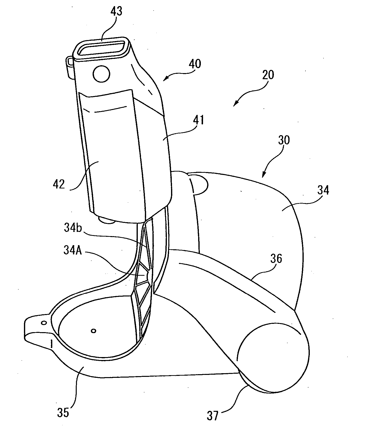
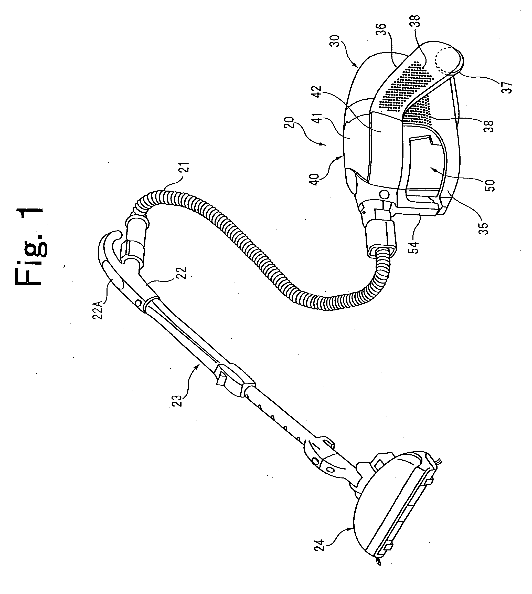
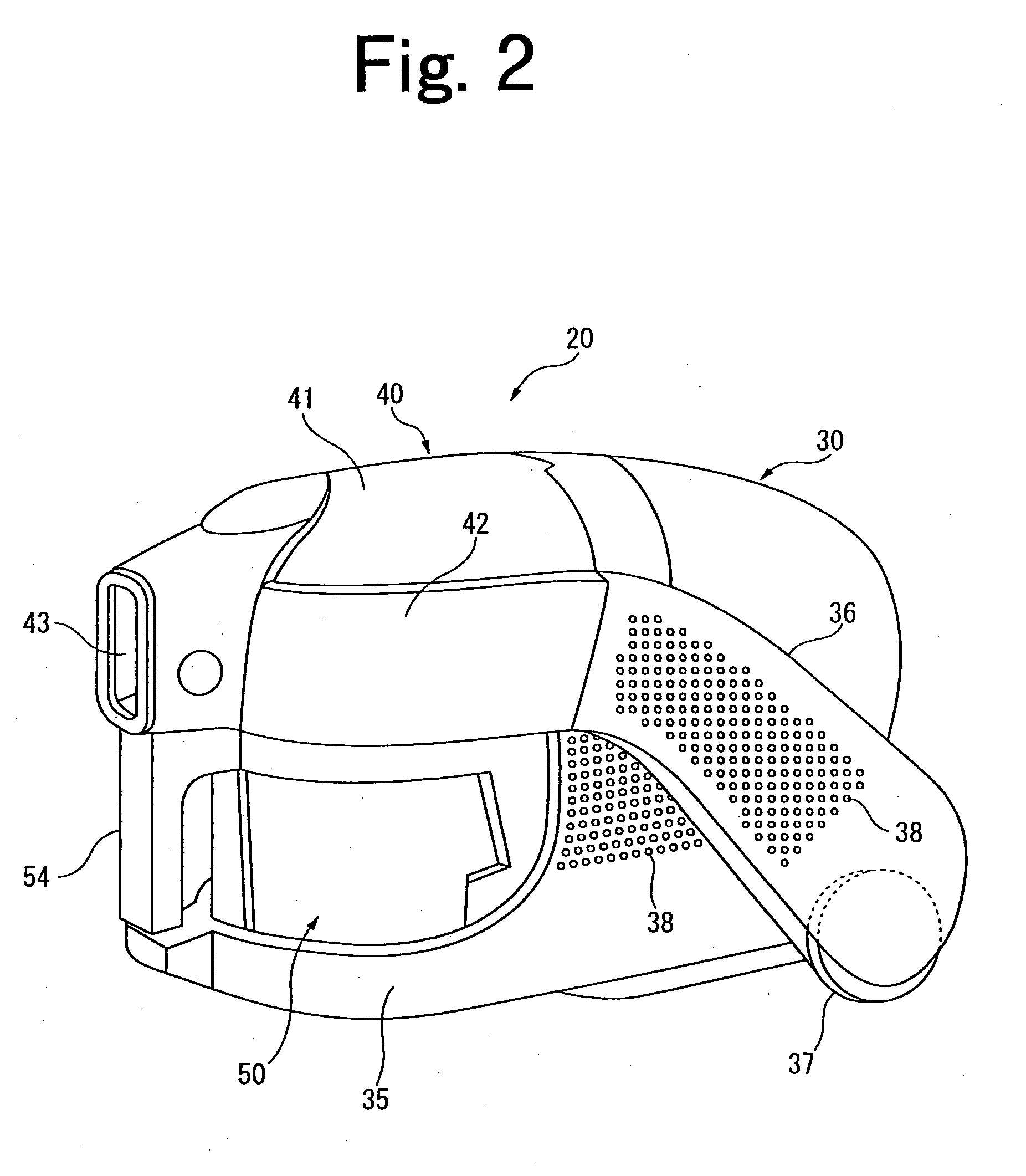
[0111]FIGS. 10-13 show an electric vacuum cleaner corresponding to the present invention. The same reference numbers indicated in FIGS. 1-8 are given for the parts identical or resembles to the structure of the embodiment shown in FIGS. 1-8, and their descriptions are omitted.

[0112] The dust separation section 60 in the second embodiment of the present invention has, as mentioned above, the tubular filter 62 formed with the passage 61 which is in a tubular shape and a strike member (tubular body) provided with the strike section 63 which is set at the other end opening 62B of the tubular filter 62. As shown in FIGS. 10 and 11, a diameter D1 of the one end opening 62A of the tubular filter 62 is formed larger than a diameter d of the suction opening (air inflow opening) 52 of the container case body 53, and a diameter D2 of the other end opening 62B of the tubular filter 62 is formed larger than a diameter of its suction opening 52. That is to say, the diameter d of the suction openi...

third embodiment

[0150]FIGS. 14 and 15 show an electric vacuum cleaner corresponding to the present invention. The same reference numbers indicated in FIGS. 1-8 are given for the parts identical or resembles to the composition of the embodiment shown in FIGS. 1-8, and their descriptions are omitted.

[0151] The dust separation section 60 in the third embodiment of the present invention has, as mentioned above, the tubular filter 62 forming the passage 61 which is in a tubular shape and the strike member (tubular body) provided with the strike section 63 which is provided at the other end opening 62B of the tubular filter 62. As shown in FIGS. 14 and 15, a diameter d1 of the one end opening 62A of the tubular filter 62 is formed larger than a diameter d2 of the suction opening (air inflow opening) 52 of the container case body 53, and a diameter d3 of the other end opening 62B of the tubular filter 62 is formed smaller than the diameter d2 of its suction opening 52.

[0152] Here, when the air containing...

sixth embodiment

[0252]FIGS. 24 and 25 show an electric vacuum cleaner corresponding to the present invention. The same reference numbers indicated in FIGS. 1-8 are given for the parts identical or resembles to the structure of the embodiment shown in FIGS. 1-8, and their descriptions are omitted.

[0253] In the sixth embodiment of the present invention, it is constituted that when the wind velocity going straight of the passage 61 of the tubular filter 62 increases, the air going straight through the passage peels off the dust attached to the net filter F2. On this occasion, as an angle a between a peripheral wall 62S and a center line L of the tubular filter 62 is set virtually 30 degrees, the wind going straight through the passage 61 hits the entire surface of the net filter F2 equally, and the wind becomes easier to flow along the surface of the net filter F2, consequently the dust attached to the net filter F2 becomes easier to be peeled off.

[0254] Next, operation on the electric vacuum cleaner...


PUM


Abstract

A dust separation section 60 is provided at a suction air passage leading from a suction opening (connection opening 43 or suction opening 52, suction opening 100) of a vacuum cleaner main body 20 to an intake opening (33A, 107A) of a motor fan (33, 107) to separate a dust sucked from the suction opening (connection opening 43 or suction opening 52, suction opening 100) with an air and a dust collection section (dust collection room section 55, dust collection room 104) provided at the suction air passage for collecting the dust separated from the air from the dust separation section 60. Moreover, the dust separation section 60 of this electric vacuum cleaner has a dust guiding space adapted to inflow the dust sucked from the suction opening (connection opening 43 or suction opening 52, suction opening 100) from an one end and for guiding the dust that flows in from an other end to the dust collection section by an inertia force, and an air guiding air passage is provided to be communicated with a midstream of the dust guiding space and is communicated with the intake opening (64, 102H) of the motor fan (33, 107) without passing through the dust collection section.

Description

TECHNICAL FIELD [0001] The present invention relates to an electric vacuum cleaner provided with a dust separation section for separating a sucked dust and a dust collection section for collecting the dust. BACKGROUND ART [0002] Heretofore, there have been known an electric vacuum cleaner provided with a cyclone system as shown in FIG. 34 (for example, see Japanese Patent Laid Open No. 2001-104223). [0003] The electric vacuum cleaner is provided with a dust cup 1 whose upper part is opened and a motor fan 2 for causing inside of the dust cup 1 to be negatively pressured or the like. An intake vent 3 is formed at a peripheral wall 1A of the dust cup 1 and the intake vent 3 is communicated with a suction opening body 4 for sucking a dust through an intake passage 5. [0004] The dust sucked from the suction opening body 4 is sucked inside of the dust cup 1 from the intake vent 3 of the duct cup 1 through the intake passage 5. A spiral flow is generated inside of the dust cup 1, thereby ...

Claims


Application Information

Patent Timeline
Patent Type & Authority Applications(United States)
IPC IPC(8): A47L9/10A47L9/12A47L9/16
CPCA47L9/102A47L9/122A47L9/1666A47L9/165A47L9/127A47L9/10A47L9/00
Inventor TAKEMOTO, RITSUOTANAKA, MASATOSHIYOKOYAMA, HIROSHISUZUKI, HITOSHIEBE, KIYOSHITSUCHIYA, YOSHIHIROTANAKA, AINAKATOGAWA, YASUSHIOSHIMA, IKUOMAEDA, YUTAKA
Owner TOSHIBA LIFESTYLE PROD & SERVICES CORP
Learn More