Corner protectors

a protector and corner technology, applied in the field of corner protectors, can solve the problems of more expensive materials produced, and achieve the effect of convenient frame insertion

Inactive Publication Date: 2005-07-14
JUPITER MOLDINGS
View PDF8 Cites 14 Cited by
  • Summary
  • Abstract
  • Description
  • Claims
  • Application Information

AI Technical Summary

Benefits of technology

[0013] Making the protector out of a plastics material has other advantages. It makes it possible for the protector to be translucent and indeed to be wholly or partially transparent without any extra manufacturing cost and with no adverse effect at all on its inherent strength and protective capabilities. It can also be self-coloured with attractive results.
[0024] A further degree of lead for the ready insertion of a frame corner into the protector may be provided by arranging for the two open edges of the protector to have a slight flange-like protrusion, but at opposite ends of the protector. Thus each flange may act as a kind of stop against which the frame corner may abut, the frame being subsequently readily inserted into the protector itself. It is advantageous if each flange occupies approximately one-half the length of its associated open edge.

Problems solved by technology

This lack of damage to the protector itself means that it can be produced in more expensive materials than the traditional laminated or corrugated staple-fixed protectors reviewed above.

Method used


Image

  • Corner protectors
  • Corner protectors
  • Corner protectors

Examples


Embodiment Construction

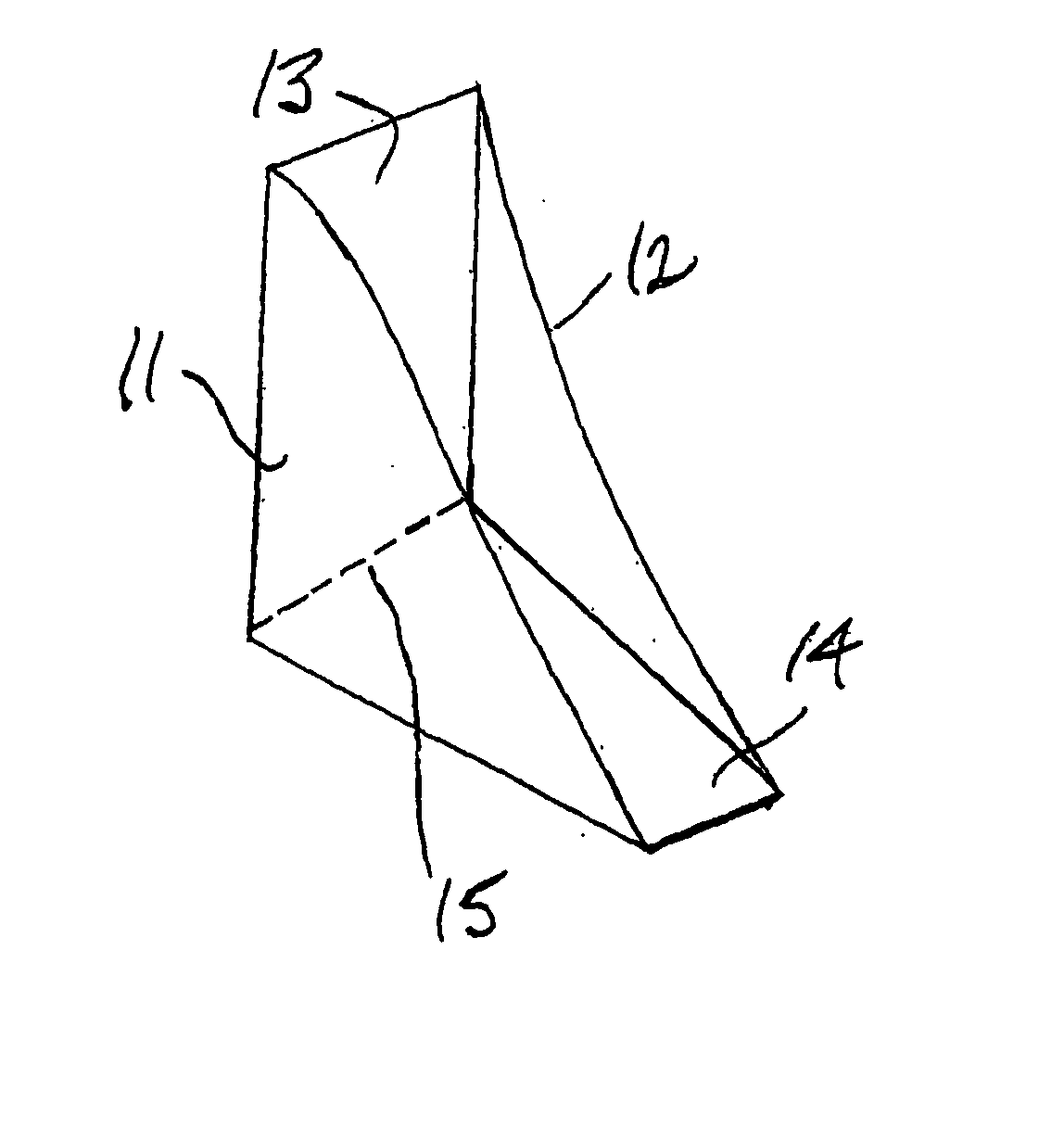
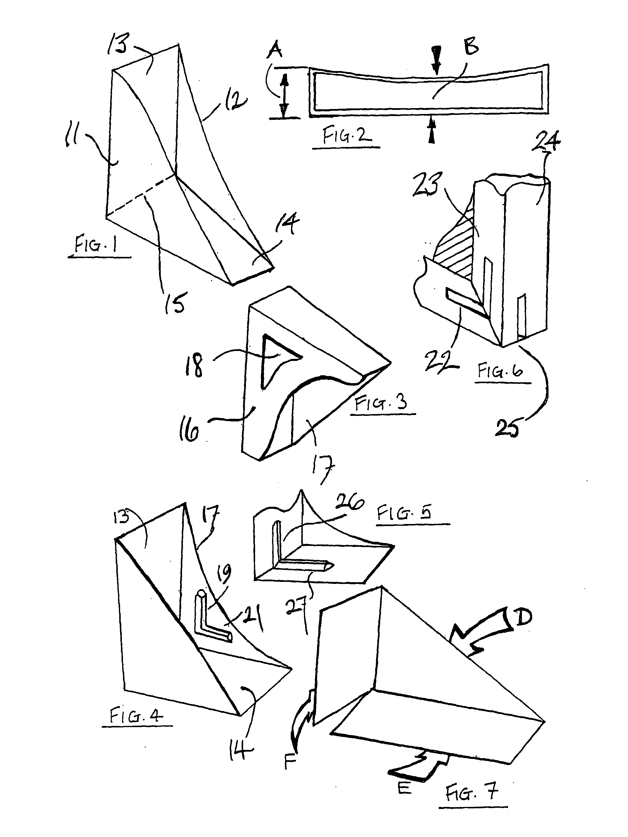
[0047] The corner protector of FIG. 1 is intended to protect one of the four corner regions of a wooden picture frame when the frame is in storage, transit or retail display. It is made from resilient plastics material such as polypropylene and it is both translucent and transparent throughout allowing bar code scanning of the price ticket inserted between the corner and the frame. Its two triangular walls 11, 12 together with its rectangular bases 13 and 14 are formed integrally as one continuous moulding and the walls 11, 12 and the bases 13, 14 of a similar thickness as one another and each the same uniform thickness throughout their respective extents.

[0048] As FIG. 1 attempts to show, wall 12 is noticeably bowed towards wall 11. FIG. 2 shows this more clearly. The gap A between the two triangular walls 11 and 12 is appreciably (although not excessively) greater than the gap B. Gap A is the distance between walls 11 and 12 where they join integrally bases 13 and 14. Gap B is th...


PUM


Abstract

A corner protector has a pair of opposite frame embracing faces which are resilient and bowed so that, in use, the corner region of a frame to be protected must force its way into position on between the opposite faces of the protector and will thereafter be frictionally gripped between them until the protector is subsequently released by pulling it off against the frictional resistance. Frame-gripping ribs may be incorporated on the major faces of the protector and in addition the protector may be tapered outwardly from its apex to its open mouth to provide a lead for insertion of the frame. To provide a still greater lead, the open edges of the protector may each be given a slight flange extension, but at opposite ends of the two edges.

Description

FIELD OF THE INVENTION [0001] The invention relates to corner protectors. [0002] In this patent specification, a corner protector is a fitment so sized and shaped as to embrace a corner region of a picture frame, poster card sheet, mounted art print, shrink-wrapped art print, mirror, sheet material or the like, between opposite surfaces in a releasable manner so as to afford temporary protection to the corner edges whilst the picture frame etc is in storage or in transit and in retail display. THE STATE OF THE ART AS KNOWN TO THE APPLICANT [0003] Corner protectors are in widespread use and are conventionally made of stiff laminated and / or corrugated card, folded up into a generally triangular shape, and defining in end elevation a rectangular opening into which the corner region of the picture frame is inserted. [0004] Usually the triangular face of such a conventional card-folded protector is then stapled or taped to the back of the wooden frame of the picture so as to stop it comi...

Claims


Application Information

Patent Timeline
Patent Type & Authority Applications(United States)
IPC IPC(8): B65D81/05
CPCB65D2581/055B65D81/057
Inventor DURRANT, SAM
Owner JUPITER MOLDINGS
Why Eureka
Try Eureka