Vehicle body side structure

a side structure and vehicle technology, applied in the field of vehicle body structure, can solve the problems of difficult to expect a great improvement in strength, and achieve the effects of improving strength, and reducing the risk of collision

Inactive Publication Date: 2005-07-14
NISSAN MOTOR CO LTD
View PDF6 Cites 17 Cited by
  • Summary
  • Abstract
  • Description
  • Claims
  • Application Information

AI Technical Summary

Benefits of technology

[0010] In recent years, there has been an increasing demand for more versatile vehicle body structures due to diversification in the size and shape of vehicles. Accordingly, there is a need for more practical measures for achieving a high degree of control over the mode of the inward movement of center pillar and significantly increasing the strength of the vehicle body.
[0011] In view of these needs, the object of the present invention is to provide a vehicle body structure that can efficiently transfer / disperse a load imparted to a pillar member during a side collision from the pillar member to the side roof rail and side sill or other frame members that are connected to the upper and lower ends of the pillar member, there by making it possible to reduce the weight of the pillar member while achieving increased strength. The invention accomplishes this goal by holding the shape of the transversely inwardly deforming pillar member in a substantially linear state.

Problems solved by technology

It has been discovered that in a conventional side structure of a vehicle body as disclosed in Japanese Patent No. 335781 that since the lower section of the center pillar bends into the passenger compartment during the initial stage of a collision due to the strength discontinuity, the strength of such a conventional vehicle body is determined by its bending strength, and it is difficult to expect a great improvement in strength.

Method used


Image

  • Vehicle body side structure
  • Vehicle body side structure
  • Vehicle body side structure

Examples


first embodiment

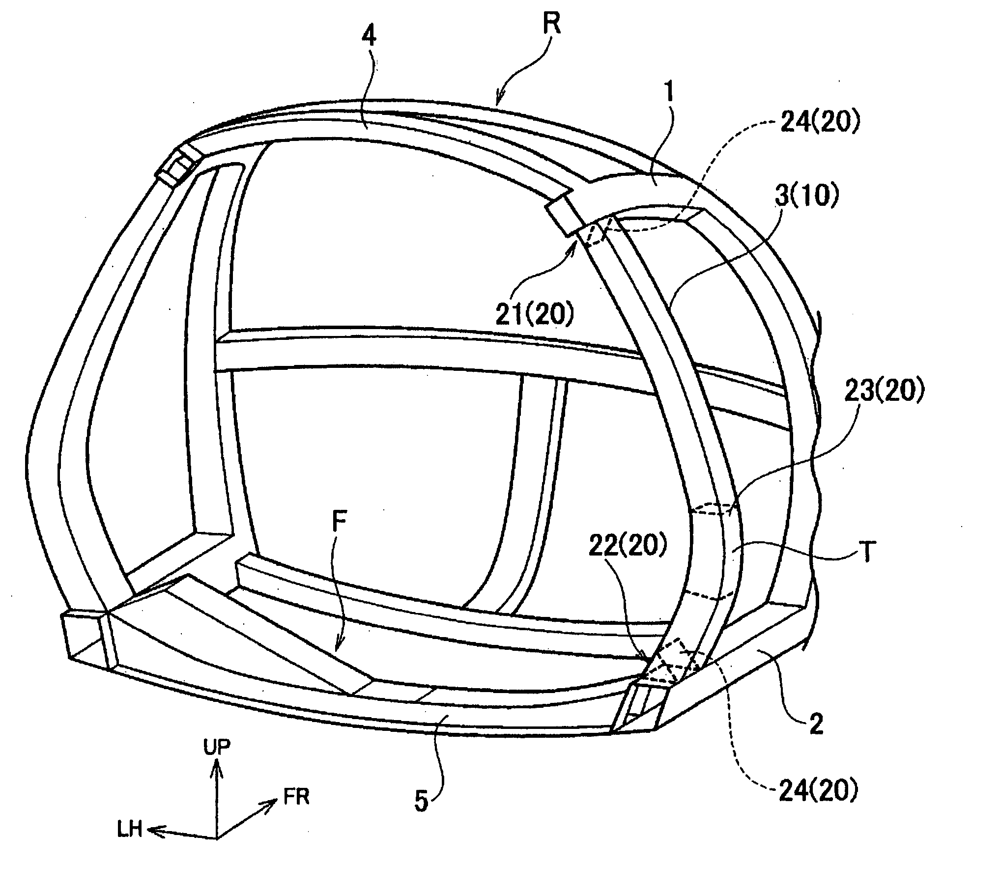
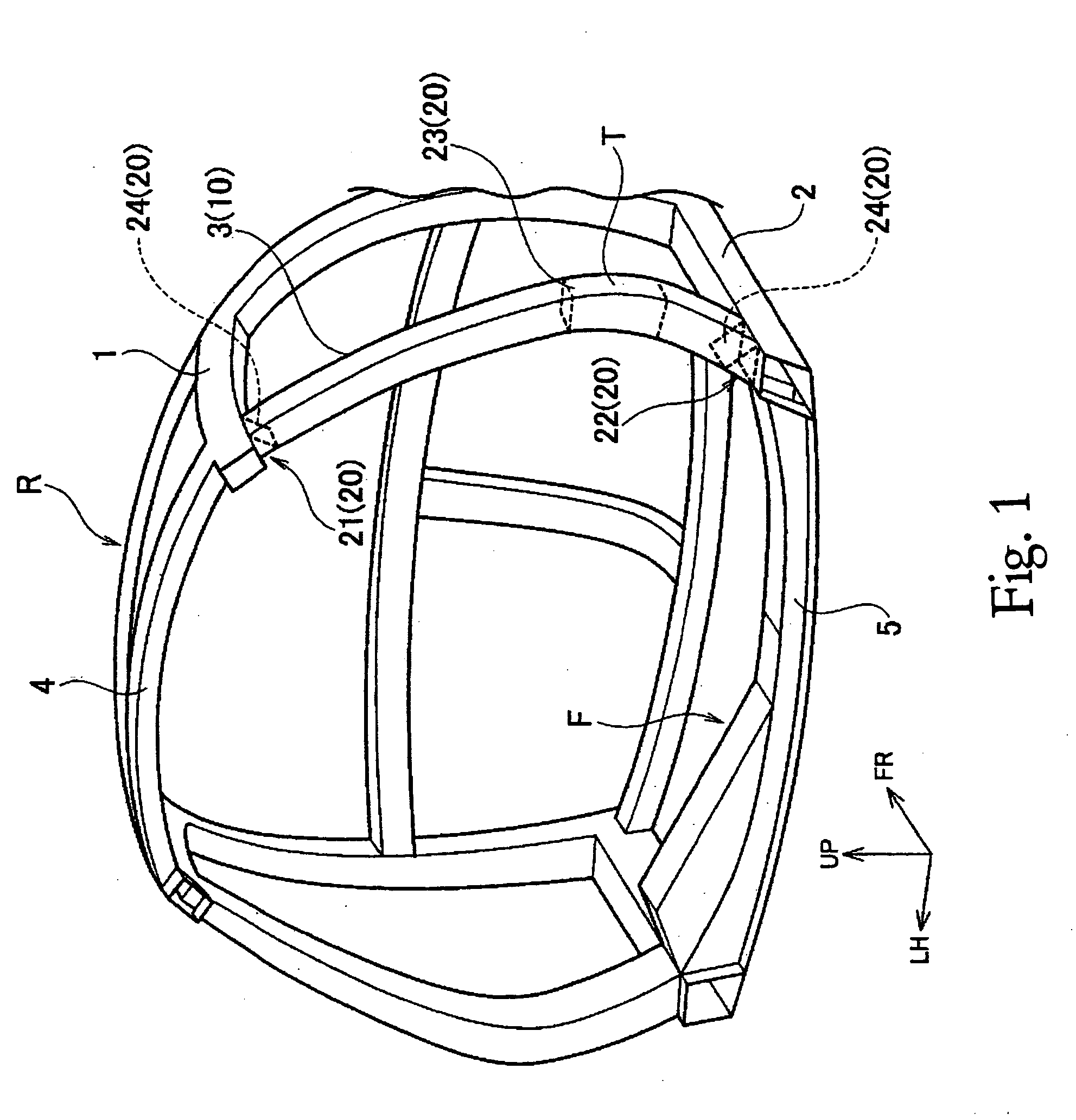
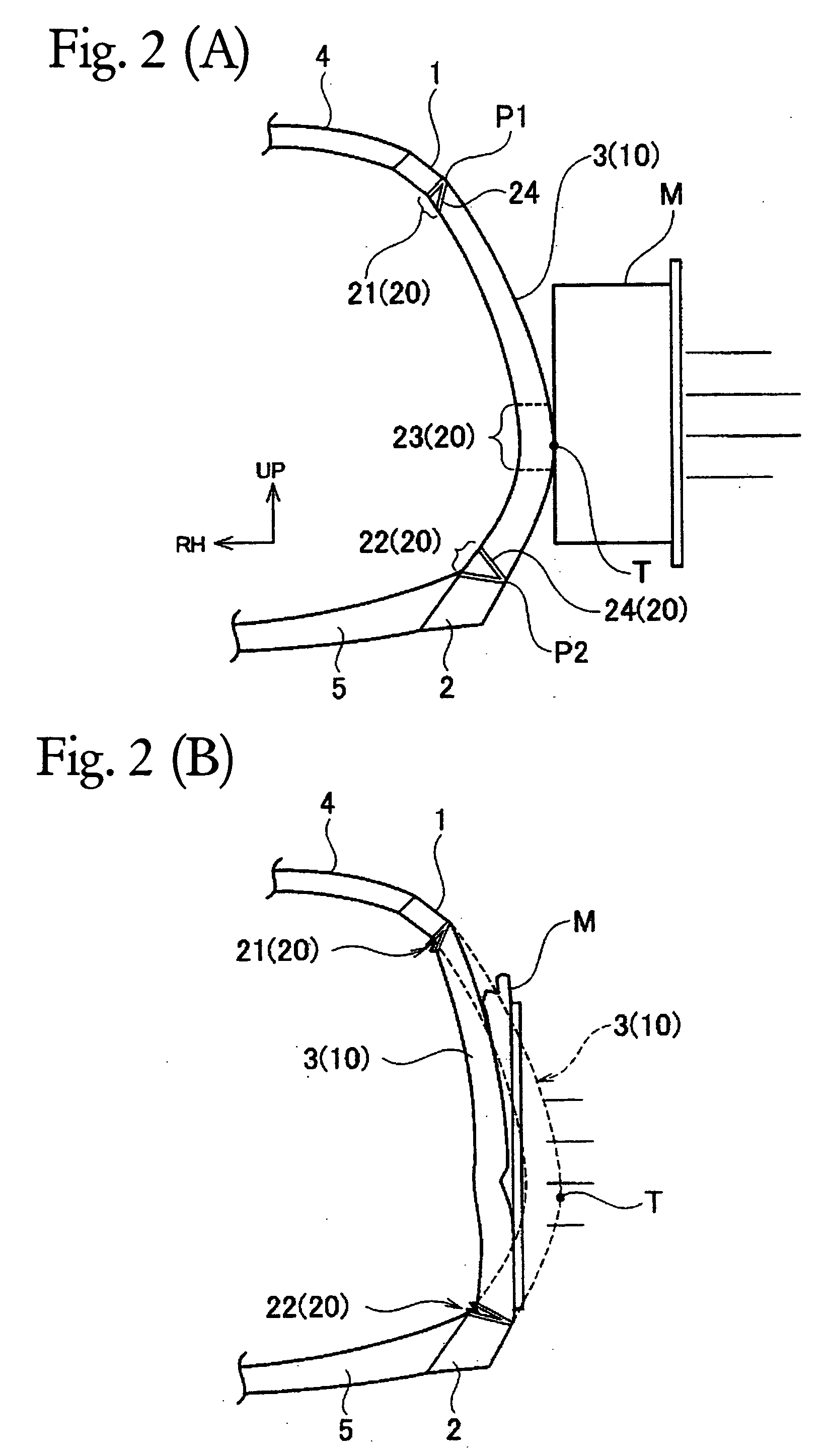
[0039] Referring initially to FIGS. 1-3, a vehicle body structure is illustrated in accordance with a first embodiment of the present invention. FIG. 1 is a rear perspective view of a passenger compartment portion of a vehicle body frame that includes a vehicle body structure in accordance with a first embodiment of the present invention. FIG. 2(A) is a schematic view illustrating the vehicle body structure of FIG. 1 just prior a side collision to illustrate a deformation mode of the first embodiment of the present invention during a side collision. FIG. 2(B) is a schematic view illustrating the vehicle body structure of FIG. 1 after the side collision of FIG. 2(A) to illustrate the deformation mode of the first embodiment of the present invention during a side collision. FIG. 3 is a graph comparing the vehicle body reaction force characteristic of the first embodiment to that of a conventional vehicle body structure during a side collision.

[0040] As shown in FIG. 1, the vehicle bo...

second embodiment

[0058] Referring now to FIGS. 4 to 6(B), a vehicle body structure in accordance with a second embodiment will now be explained. In view of the similarity between the first and second embodiments, the parts of the second embodiment that are identical to the parts of the first embodiment will be given the same reference numerals as the parts of the first embodiment. Moreover, the descriptions of the parts of the second embodiment that are identical to the parts of the first embodiment may be omitted for the sake of brevity.

[0059]FIG. 4 is a side perspective view of a vehicle body frame structure that includes a vehicle body structure in accordance with a second embodiment of the present invention. FIG. 5(A) is a cross sectional view of the center pillar of the second embodiment taken along section lines A-A of FIG. 4. FIG. 5(B) is a cross sectional view of the center pillar of the second embodiment taken along section lines B-B of FIG. 4. FIG. 5(C) is a cross sectional view of the ce...

third embodiment

[0074] Referring now to FIGS. 7, 8(A) and 8(B), a vehicle body structure in accordance with a third embodiment will now be explained. In view of the similarity between the first and third embodiments, the parts of the third embodiment that are identical to the parts of the first embodiment will be given the same reference numerals as the parts of the first embodiment. Moreover, the descriptions of the parts of the third embodiment that are identical to the parts of the first embodiment may be omitted for the sake of brevity.

[0075]FIG. 7 is a side perspective view of a vehicle body frame structure that includes a vehicle body structure in accordance with a third embodiment of the present invention. FIG. 8(A) is a schematic view illustrating the vehicle body structure of FIG. 7 just prior a side collision to illustrate a deformation mode of the second embodiment of the present invention during a side collision. FIG. 8(B) is a schematic view illustrating the vehicle body structure of ...


PUM


Abstract

A vehicle body structure having a pillar member maintains the shape of a pillar member in a substantially linear state when the pillar member deforms inward toward the passenger compartment during a side collision. The pillar member has a collision force converting structure that is constituted by the curved shape of the pillar member. When a side collision force is imparted to the pillar member, the collision force converting structure converts it into and maintains it as a force acting on the pillar member in the lengthwise direction of the pillar member. Thus, the collision force is absorbed as a lengthwise compressive load in the pillar member. A shape maintaining structure restricts the inward deformation of the pillar member 3 toward the passenger compartment and holds the pillar member in a substantially linear shape to increase the efficiency with which the collision load is transferred to the side roof rail and side sill.

Description

CROSS-REFERENCE TO RELATED APPLICATIONS [0001] This application claims priority to Japanese Patent Application No. 2004-5465. The entire disclosure of Japanese Patent Application No. 2004-5465 is hereby incorporated herein by reference. BACKGROUND OF THE INVENTION [0002] 1. Field of the Invention [0003] The present invention generally relates to a vehicle body structure for an automobile. More specifically, the present invention relates to a vehicle body side structure that is configured to absorb the energy of a side impact. [0004] 2. Background Information [0005] Some conventional vehicle body structures have been proposed in which a strength discontinuity is provided in a lower portion of a center pillar having a closed cross sectional structure. During a side collision, the structure bends into the passenger compartment in an appropriate manner at the strength discontinuity, thus preventing localized bending at the middle area and the upper area of the center pillar. As a result...

Claims


Application Information

Patent Timeline
Patent Type & Authority Applications(United States)
IPC IPC(8): B60R99/00B62D21/15B62D25/02B62D25/04
CPCB62D21/157B62D25/04B62D25/025B62D25/02
Inventor SAEKI, HIDETSUGU
Owner NISSAN MOTOR CO LTD
Why Eureka
Try Eureka