Electromagnetic relay

Active Publication Date: 2005-07-14
ORMON CORP
View PDF7 Cites 29 Cited by
  • Summary
  • Abstract
  • Description
  • Claims
  • Application Information

AI Technical Summary

Benefits of technology

[0015] According to the aspect, the traveling of vibration noise, which travels through a solid, can be suppressed since the yoke spanned across the l

Problems solved by technology

However, the sealed relay apparatus has a problem that impact noise is caused when the p

Method used


Image

  • Electromagnetic relay
  • Electromagnetic relay
  • Electromagnetic relay

Examples


Embodiment Construction

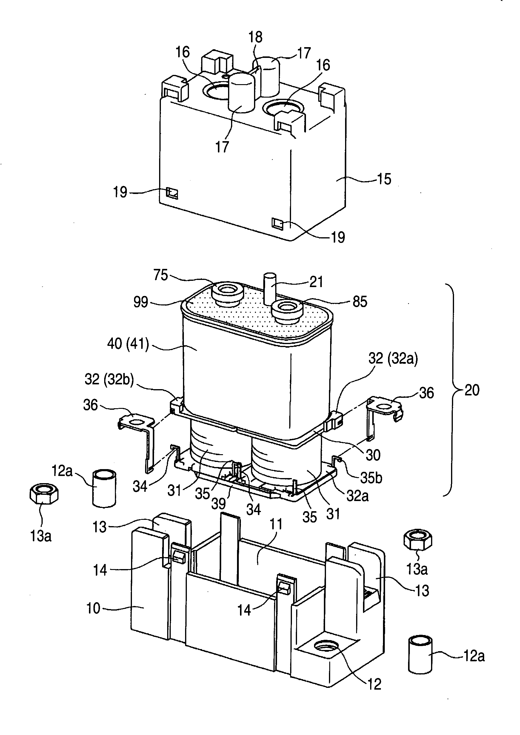
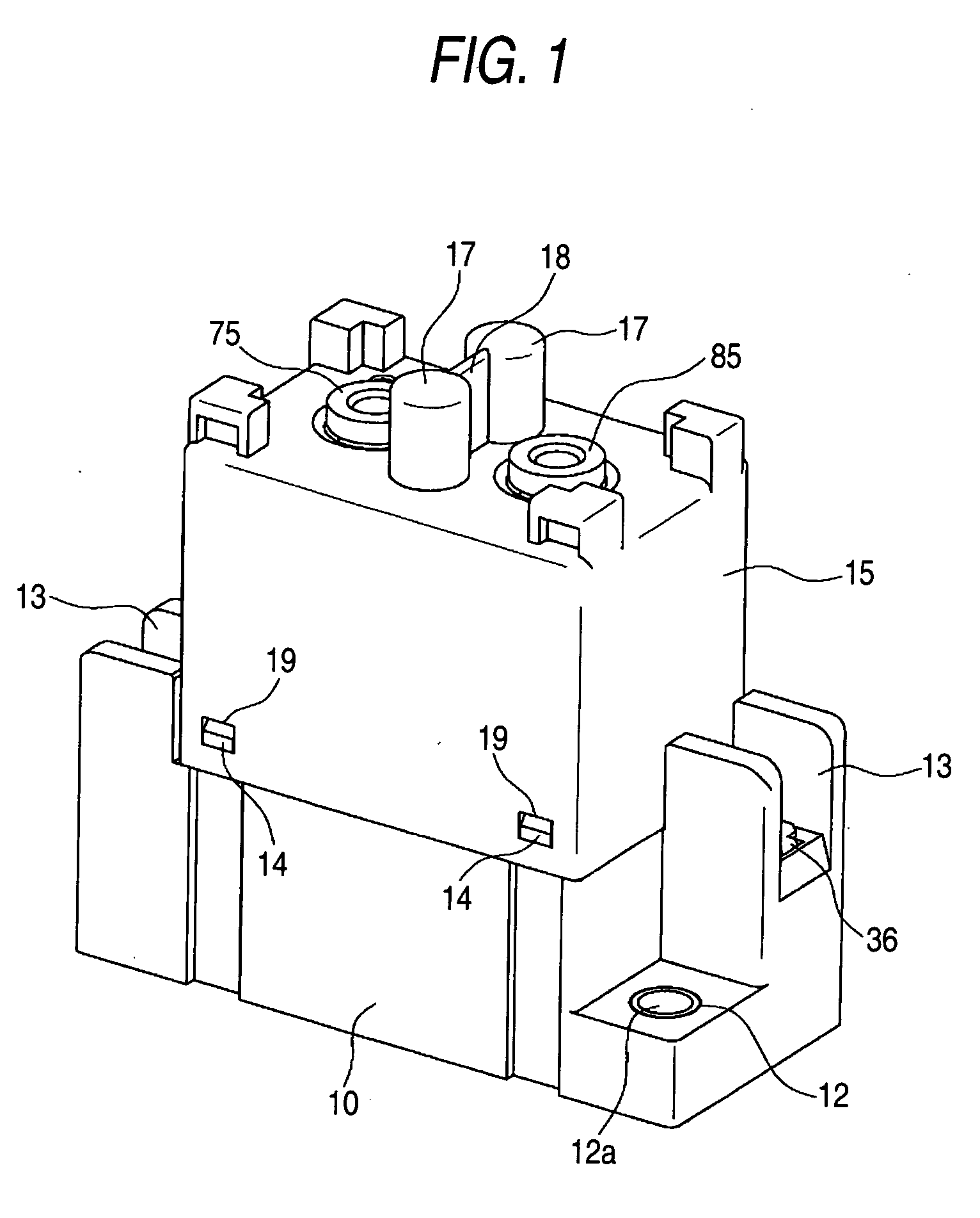
[0034] An embodiment according to the invention will be described with reference to FIGS. 1 to 18B.

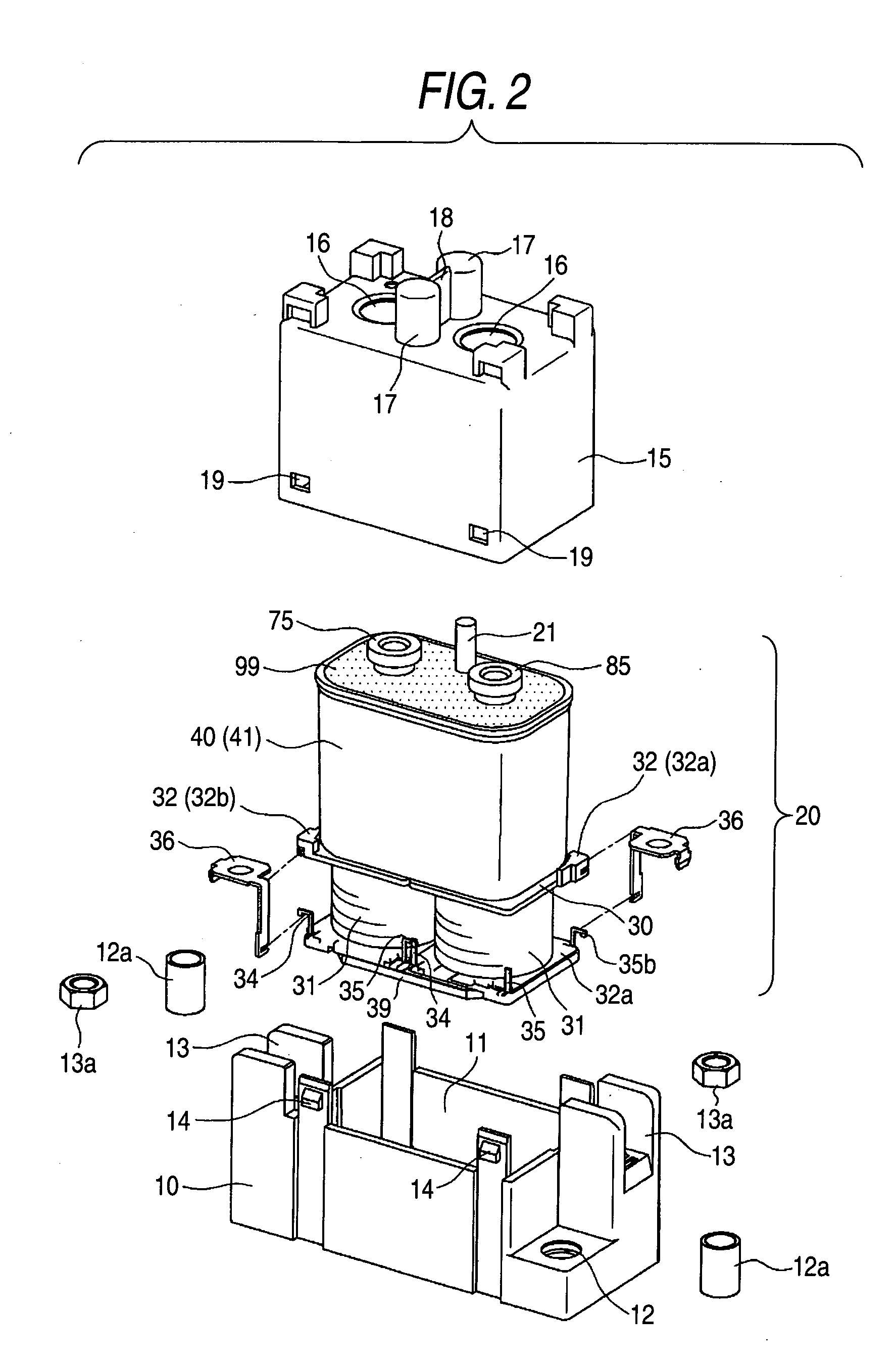
[0035] This embodiment is a case that the invention is applied to a direct current load switching relay, and, as shown in FIGS. 1 and 2, a relay body 20 is accommodated in a space enclosed by a box case 10 and box cover 15, which are integrated.

[0036] As shown in FIG. 2, the box case 10 has a concave part 11 that can accommodate an electromagnet block 30, which will be described later, and includes fixing through-holes 12 at a pair of diagonal corners of the plane and connecting concaves 13 at remaining corners of the plane. A strengthening tube body 12a is press-fitted into each of the through-hole 12, and a connecting nut 13a is fitted into each of the connecting concaves 13.

[0037] The box cover 15 has a form that can be fitted into the box case 10 and can accommodate a sealing case block 40, which will be described later. Furthermore, the ceiling surface of the box cover 15 has c...


PUM


Abstract

An electromagnetic relay includes an electromagnet block having coils wound about the bodies of spools through which iron cores are provided. The electromagnet block is accommodated in a concave part that opens upward of a box-shaped case such that the shaft centers of the iron cores can be orthogonal to the bottom surface of the box-shaped case. The electromagnet block is excited and demagnetized by the passage and break of electric current through the coils so that a contact mechanism can be driven by a movable iron piece that is absorbed to and leaves magnetic pole portions at the upper ends of the iron cores. In this case, the electromagnet block is hung at the upper opening edge of the box-shaped case such that a space can be provided between the bottom surface of the box-shaped case and the electromagnet block.

Description

BACKGROUND OF THE INVENTION [0001] 1. Field of the Invention [0002] The present invention relates to an electromagnetic relay, and, more specifically, it relates to an electromagnetic relay having a sealed contact mechanism. [0003] 2. Description of the Related Art [0004] Hitherto, a sealed relay apparatus disclosed in JP-T-9-510040 is one of switching apparatus for breaking direct current. [0005] In other words, a plunger 9 touches and leaves a core center 4 based on excitation and demagnetization of coils 26 in a hollow cavity 40 so that an armature assembly 8 and armature shaft 10 integrated with the plunger 9 can slide toward the shaft center. Thus, a movable contact disk 21 touches and leaves fixed contacts 22 and 22. [0006] However, the sealed relay apparatus has a problem that impact noise is caused when the plunger 9 touches the core center 4 and cannot be absorbed and mitigated, which is noisy. SUMMARY OF THE INVENTION [0007] The invention was made in view of the problem, a...

Claims


Application Information

Patent Timeline
IPC IPC(8): H01H50/04H01H50/02H01H50/30
CPCH01H50/305H01H2050/025H01H9/443
Inventor NISHIDA, TAKESHIMASUI, YASUYUKI
Owner ORMON CORP
Why Eureka
Try Eureka