Interposer connectors with magnetic components

a technology of interposer connectors and magnetic components, applied in the direction of coupling device connection, coupling/disconnecting parts, substation equipment, etc., can solve the problem that flexibility may not have a functional benefit, and achieve the effect of increasing electrical contact force and large dimensional tolerances insensitivity

Active Publication Date: 2013-10-17
APEX TECH INC
View PDF11 Cites 122 Cited by
  • Summary
  • Abstract
  • Description
  • Claims
  • Application Information

AI Technical Summary

Benefits of technology

[0009]The interposer electrical connector systems and methods described below contain magnetic elements configured to provide any of the following capabilities: self-mating contact forces, protection of device connector structures from dust or moisture, low-profile design, relatively large dimensional tolerances insensitivity than the standard I / O connectors, mechanical flexibility, conformability to curved surfaces, articulated construction designs, and self-aligning electrical contacts. In some embodiments, flexible magnetic interconnects described in co-owned U.S. Pat. No. 8,187,006 are used to provide some of these benefits. Some embodiments include multiple permanent magnets with the same magnetic pole aligned toward the connector interface. Some embodiments include magnetic flux concentrators or pole pieces that direct the magnetic flux circuit to increase electrical contact forces. Some embodiments comprise a single magnet per mated contact pair that provides a plurality of electrical connections.
[0020]In embodiments of the methods and systems disclosed herein, there is generally no requirement for rigid printed circuit boards, rigid or resilient electrical contact structures, stiff electrical contact support structures or housings. In addition, the design of flexible printed circuit boards and other compliant contact structures may be readily customized somewhat independently from the design of the larger mechanical structure of the modules. This ability to accommodate changes allows for flexibility in design and tooling flexibility. Since electrical contact mating pairs can be designed to function substantially independently, efficiencies in designing, fabricating and testing different composite assemblies from a small number of component designs may be gained. Cost efficiencies may be gained in the nesting or “panelization” of the flexible printed circuits, fabrication of mechanical structures for modules and standardization of a limited number of parts.

Problems solved by technology

In this case, a flexible printed circuit in a description may be constructed from materials that are not flexible in bulk form, or the flexibility may have no functional benefit beyond thinness.

Method used


Image

  • Interposer connectors with magnetic components
  • Interposer connectors with magnetic components
  • Interposer connectors with magnetic components

Examples


Embodiment Construction

[0103]This detailed description defines the meaning of terms used herein and specifically describes embodiments in order for those skilled in the art to practice the invention. The description and drawings of specific embodiments are provided as examples of the principles and not to limit the invention to the specific embodiments illustrated and described. Characteristics of an embodiment described herein may be combined with characteristics of other embodiments in a suitable manner without limitation.

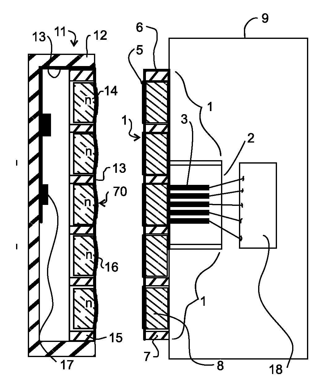
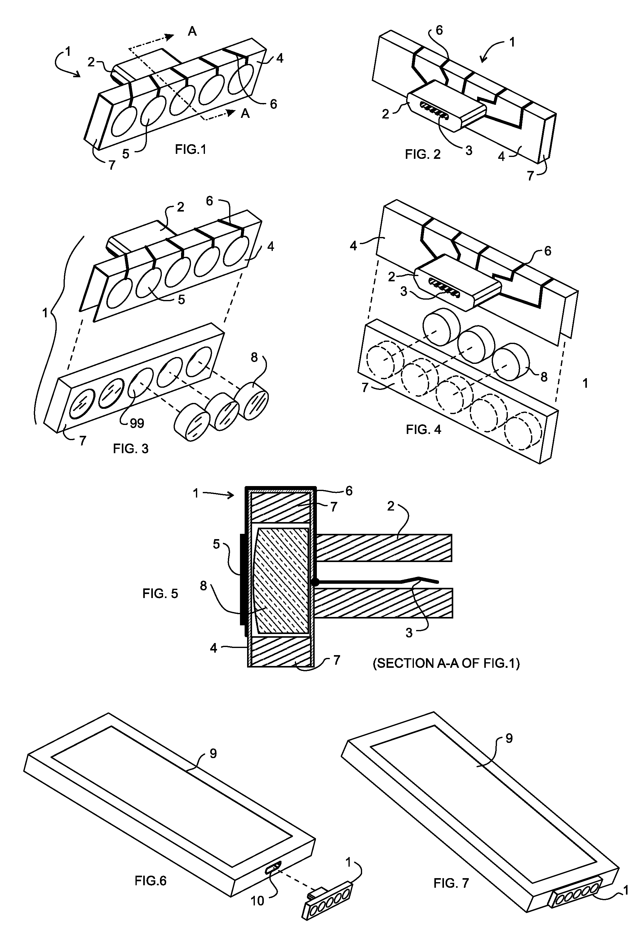
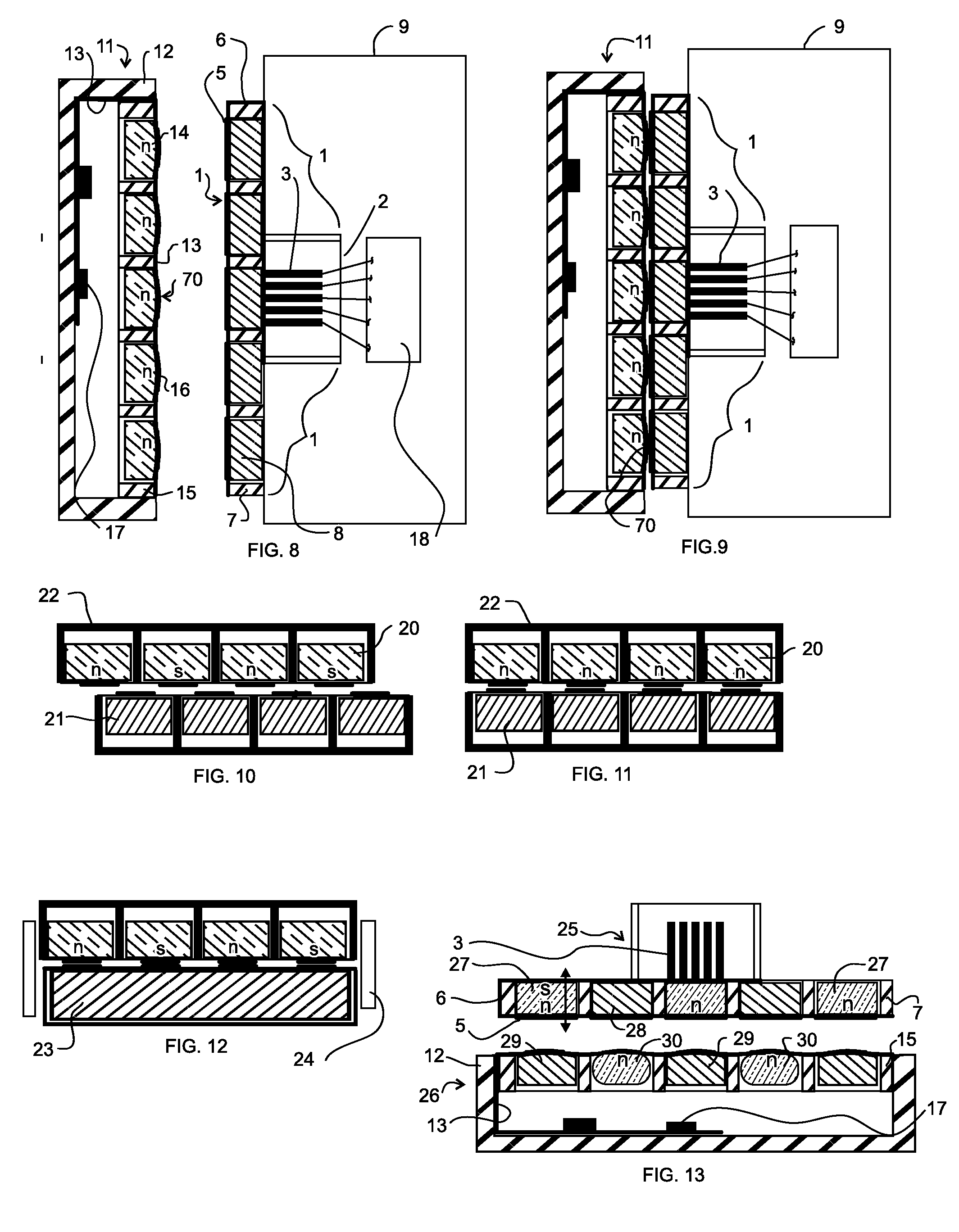
[0104]FIG. 1 through FIG. 9 show an embodiment of interposer connector 1, designed to interface with a conventional main I / O connector 10 of an electronic device 9, which may be, for example, a smart phone, tablet device, portable computer, or other electronic assembly, whether portable or not. Typically, device 9 will have at least one main I / O connector 10, such as a standard USB, micro-USB, or custom I / O connector (APPLE Inc. and others), utilized for battery charging and operating ...


PUM


Abstract

Disclosed are interposer electrical connector embodiments including magnetic components used to facilitate interconnection of peripheral devices to standard input / output, or “I / O”, connectors (such as USB connectors) of devices such as mobile communications products (e.g. smart phones, tablets, and personal computers). The interposer connector embodiments disclosed include those in which a plurality of discrete permanent magnets are arranged with magnetic poles aligned in the same orientation perpendicular to and on one side of the electrical interface. Other embodiments include a plurality of bar permanent magnets located on opposite sides of the interface with all poles of the same type directed at the interface, but each one opposing a ferromagnetic element. These arrangements provide self-aligning capabilities useful for electrical connections that have restrictions on visibility or connection approach geometries. Other embodiments have a single magnet per mated connector pair and magnetic pole pieces and / or actuators to concentrate magnetic flux providing the magnetic attractive force for a plurality of electrical connections.

Description

CROSS-REFERENCE TO RELATED APPLICATIONS[0001]This disclosure claims priority of U.S. provisional patent application No. 61 / 655,483 filed on Jun. 5, 2012 and U.S. provisional patent application No. 61 / 786,037 filed on Mar. 14, 2014 and U.S. non-provisional application Ser. No. 13 / 105,091 filed May 11, 2011 and U.S. non-provisional patent application Ser. No. 12 / 698,731 filed on Feb. 2, 2009 which issued on May 29, 2012 as U.S. Pat. No. 8,187,006, all of which are incorporated herein by reference in their entirety.COPYRIGHT NOTICE[0002]A portion of the disclosure of this patent contains material that is subject to copyright protection. The copyright owner has no objection to the reproduction by anyone of the patent document or the patent disclosure as it appears in the Patent and Trademark Office patent file or records, but otherwise reserves all copyright rights whatsoever.BACKGROUND OF THE INVENTION[0003]1. Field of the Invention[0004]This disclosure deals with electrical connection...

Claims


Application Information

Patent Timeline
Patent Type & Authority Applications(United States)
IPC IPC(8): H01R13/62
CPCH01R13/6205H01R11/30H01R13/645H04M1/0274
Inventor RUDISILL, CHARLES ALBERTWHITTLE, DANIEL JOHN
Owner APEX TECH INC
Why Eureka
Try Eureka