Low-profile optical mounting assembly

a technology of optical mounting and low-profile, which is applied in the field of low-profile optical mounting assemblies, can solve the problems of eye strain, discomfort and even headaches, and the physical bulk of existing designs, and achieve the effects of enhancing peripheral vision, reducing visual obscuration, and low-profile design

Active Publication Date: 2010-09-07
GEN SCI
View PDF5 Cites 6 Cited by
  • Summary
  • Abstract
  • Description
  • Claims
  • Application Information

AI Technical Summary

Benefits of technology

[0007]This invention improves upon prior-art ocular support assemblies by removing material present in the forward-looking cross-section of the outwardly extending support arms, thereby reducing visual obscuration and enhancing peripheral vision. In the preferred embodiment, the top of the outwardly extending support arm is approximate to the middle of the height of the housing, thereby resulting in a low-profile design. At the same time, the support arms are received by the housing with sliding engagement on all sides, thereby eliminating the need for ball bearings or spacers to counteract twisting. The result is a lightweight yet highly stable ocular mounting assembly.

Problems solved by technology

Excessive divergence can cause eyestrain, discomfort and even headaches.
Despite these advances, existing designs tend to be physically rather bulky, limiting peripheral vision, for example, when the practitioner looks away from the loupes. FIG. 1 is a drawing that shows front and top views of an older rack assembly, including a housing 20 into which support arms 22 are slidingly engaged to set interpupillary distance using adjusting knob 24.
However, in this case, the cross-sections 22′ of the outwardly extending support arms are nearly the same height as the housing 20′, leading to continual visual obscuration.

Method used


Image

  • Low-profile optical mounting assembly
  • Low-profile optical mounting assembly
  • Low-profile optical mounting assembly

Examples


Embodiment Construction

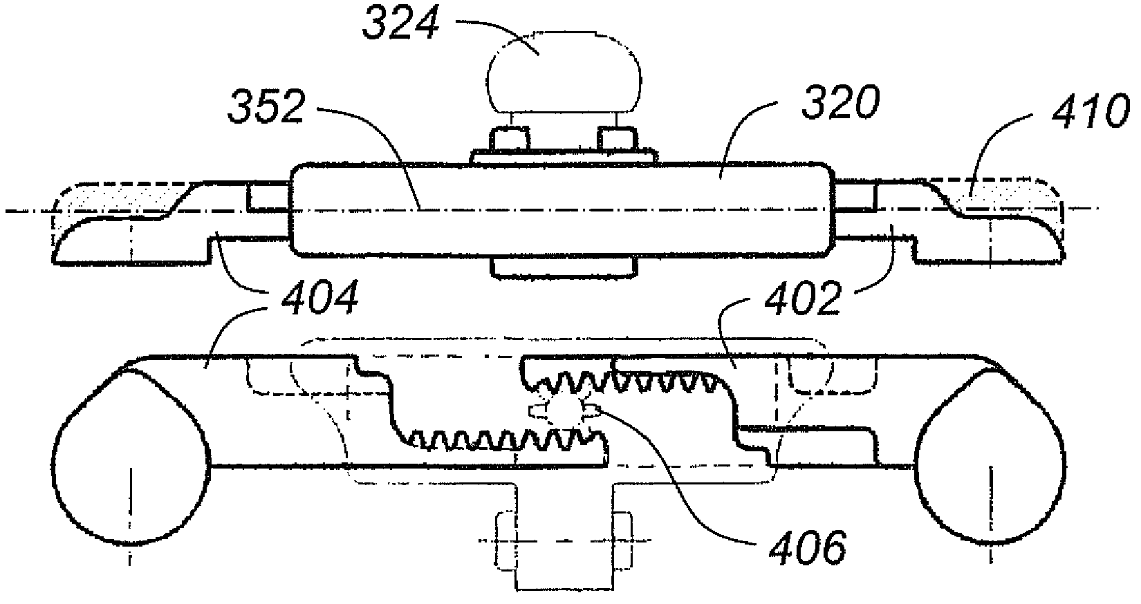
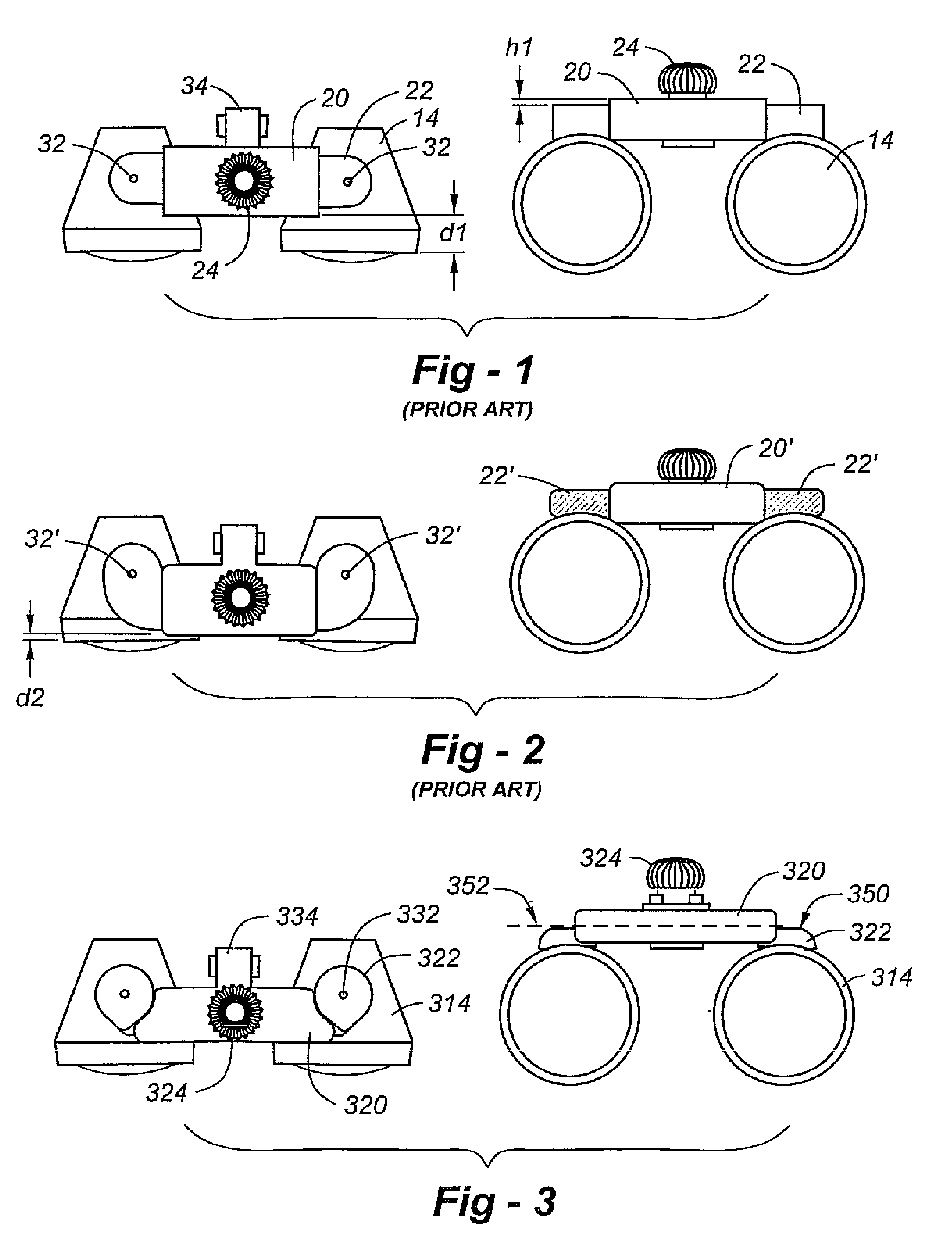
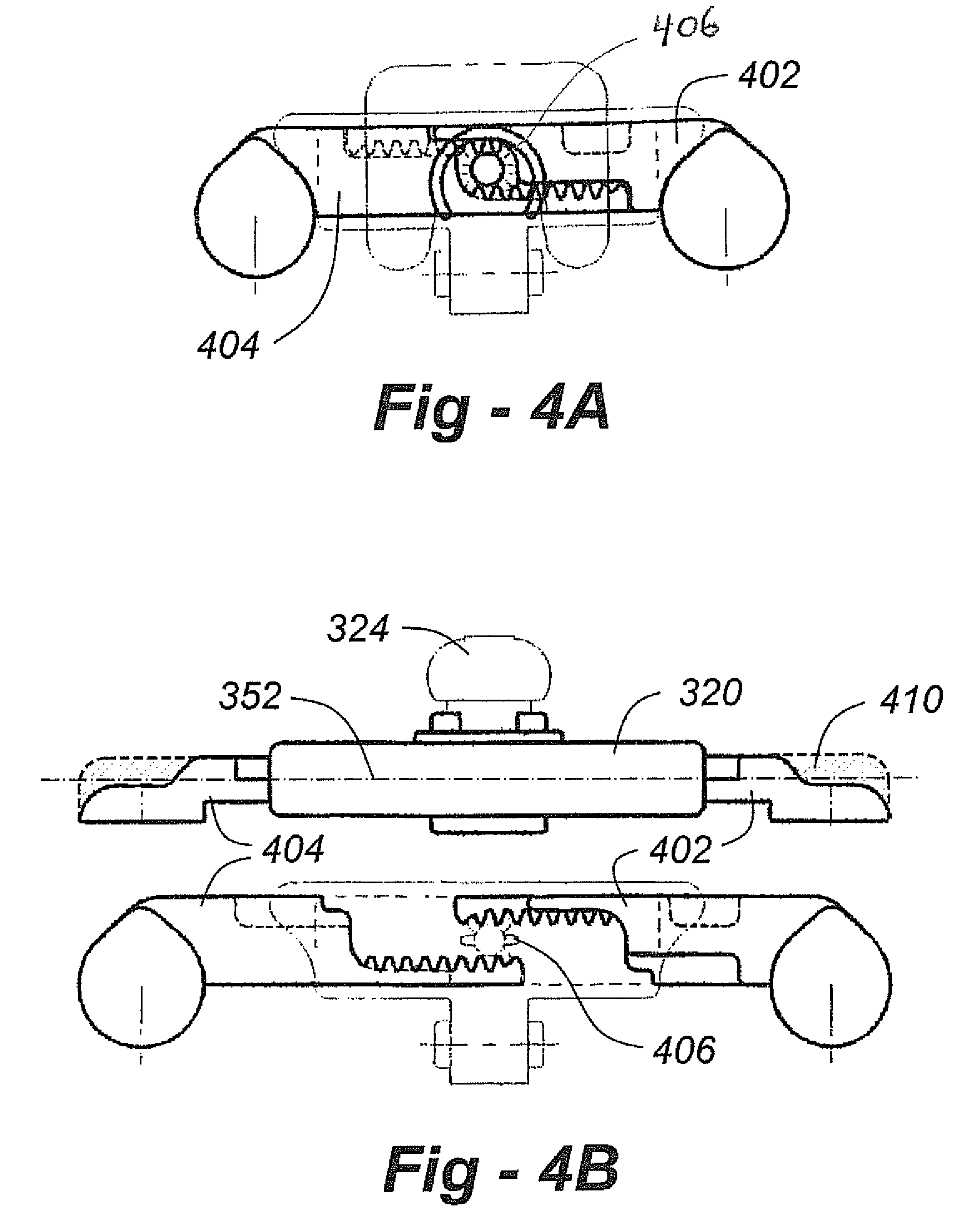
[0013]Having discussed FIGS. 1 and 2, the reader's attention is directed to FIG. 3, which shows an ocular mounting assembly constructed in accordance with the invention. The housing is shown at 320, including an outwardly extending portion 334 having side pins that engage with a hinged pivot assembly (not shown), which may be similar to, if not identical to, prior-art hinge assemblies facilitating an eyeglass or head-band mount. The adjustment knob is shown at 324, and the oculars are shown at 314.

[0014]Importantly, according to the invention, the top surface 350 of each support arm 322 has material removed, allowing the top of the support arm to be at or below the horizontal centerline 352 of the housing 320. This removed material decreases visual obscuration and enhances peripheral vision for the user. In the preferred embodiment, the dimension between the top of the arms major length to the area directly above the ocular is 0.099″+ / −0.010″ (2.51+ / −0.25 mm). The dimension from the...


PUM


Abstract

In an ocular support assembly material present in the forward-looking cross-section of the outwardly extending support arms is removed, thereby reducing visual obscuration and enhancing peripheral vision. In the preferred embodiment, the top of each outwardly extending support arm is at or below the middle of the height of the housing, thereby resulting in a low-profile design. At the same time, the support arms are received by the housing with sliding engagement on all sides, thereby eliminating the need for ball bearings or spacers to counteract twisting. The result is a lightweight yet highly stable ocular mounting assembly.

Description

FIELD OF THE INVENTION[0001]This invention relates generally to ocular mounting assemblies of the type used in surgical, medical and dental applications and, in particular, to a stable, low-profile assembly affording enhanced peripheral vision.BACKGROUND OF THE INVENTION[0002]Telescopic instruments are widely used for magnifying a work area during precision work such as delicate surgery, dental work, inspection of circuit board solder joints, and assembly of miniature parts. A typical telemicroscopic instrument includes a pair of telemicroscopic loupes which are adjustably mounted to an eyeglass frame or headband. The telescopic loupes combine the long working distance of the telescope with the high quality magnification of the microscope. This type of optical instrument provides the user, a surgeon, for example, with a magnified image of the work area with a field of view at about an arm's length.[0003]As one example, the ocular mounting assembly disclosed in U.S. Pat. No. 5,381,26...

Claims


Application Information

Patent Timeline
Patent Type & Authority Patents(United States)
IPC IPC(8): G02B23/00
CPCG02B23/18
Inventor CUMMINGS, THOMASCHANG, BYUNG JIN
Owner GEN SCI
Why Eureka
Try Eureka