
Method and system for balloon counterpulsation during aortic valve replacement

a technology for aortic valves and counterpulse, which is applied in the field of medical devices and methods, can solve problems such as harming patients, and achieve the effects of reducing the percentage of occlusion of the aortic lumen, limiting regurgitation, and maximizing the percentage of aortic luminal occlusion

Active Publication Date: 2016-04-12
HOCOR CARDIOVASCULAR TECH
View PDF18 Cites 27 Cited by
  • Summary
  • Abstract
  • Description
  • Claims
  • Application Information

AI Technical Summary

Benefits of technology

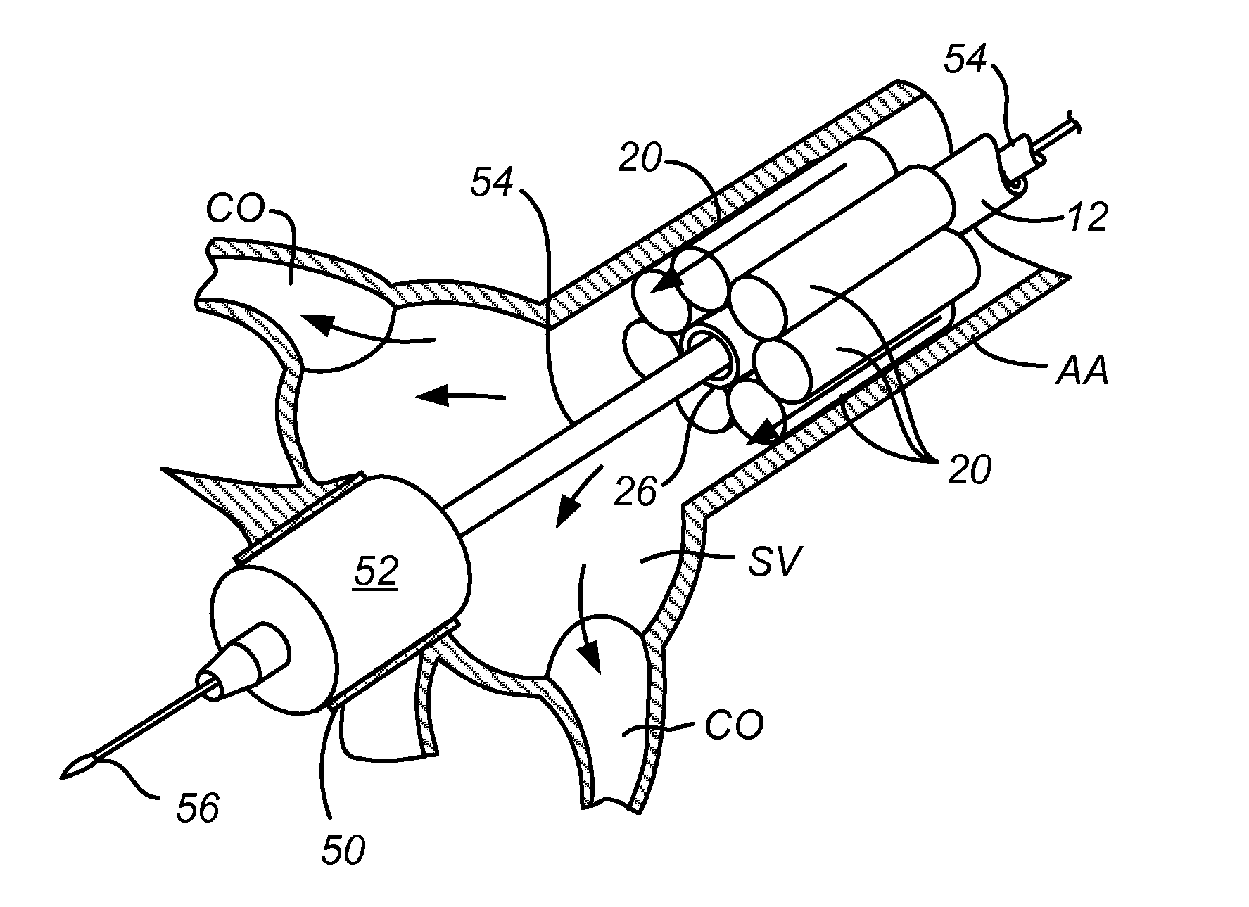
[0012]While controlled retrograde flow during ventricular diastole can be provided by fixed, partial occlusion devices positioned in the ascending aorta above the Sinus of Valsalva, as described in commonly owned applications US 2009 / 0030503 and US 2009 / 0030510, the present invention provides for variable occlusion of blood flow through the aorta so that the degree or level of occlusion can be selected and changed during different portions of the cardiac cycle (systole and diastole) as well as during different portions of the procedure, e.g., valve ablation, valve excision, prosthetic valve implantation, etc. Thus, for example, during ventricular diastole, the percentage of aortic luminal occlusion can be maximized to limit regurgitation through the aortic valve annulus while providing a sufficient level of coronary artery perfusion through the Sinus of Valsalva. During ventricular systole, in contrast, the percentage of occlusion of the aortic lumen will be lessened considerably. While some small level of occlusion will be present due to the cross-sectional area of the catheter and / or other tool which is holding the occlusion device, it is theoretically possible to reduce the additional occlusion provided by the variable occlusion device to a level close to zero. While such minimal occlusion is desirable to maximize antegrade flow through the aorta, it will usually be desirable to maintain balloons or other expandable elements in order to stabilize the catheter or other tool access (resulting in a finite but acceptable level of resistance to antegrade flow).
[0013]Methods according to the present invention for regulating aortic regurgitation during aortic valve replacement or repair procedures comprise positioning a catheter or other tool having a variable occlusion device in the ascending aorta above the Sinus of Valsalva. The occlusion device is expanded to partially occlude the aortic lumen during ventricular diastole to inhibit aortic regurgitation while allowing perfusion of the coronary arteries via the Sinus of Valsalva. During ventricular systole, however, the occlusion device is partially or fully contracted in order to reduce occlusion of the aortic lumen and lessen inhibition of antegrade blood flow from the left ventricle to the aorta. Expansion and contraction of the occlusion device is typically continued in synchrony with the cardiac cycle (diastole followed by systole) while the repair or replacement procedure is performed.
[0018]Systems according to the present invention comprise a catheter having an expandable and contractible occlusion device near its distal end. The catheter is adapted to be introduced into the aorta, and the occlusion device is sized to partially occlude the ascending aorta above the Sinus of Valsalva when fully expanded. An inflation controller is connectable to the catheter to alternatively (1) expand the occlusion device during ventricular diastole to inhibit aortic regurgitation while allowing perfusion of the coronary arteries via the Sinus of Valsalva and (2) to contract or reduce the size of the occlusion device during ventricular systole to lessen inhibition of antegrade blood flow from the left ventricle to the aorta. The systems will typically further include a sensor to detect ventricular diastole and ventricular systole. For example, a heart rhythm monitor (EKG) may be provided to detect ventricular diastole and systole. Alternatively, a pressure sensor may be provided in the system, typically on or near a distal end of the catheter, to detect ventricular diastole and systole based on pressure in the ascending aorta or elsewhere in the vasculature.
[0020]The occlusion device may have any of the various structures described above with respect to the method of the present invention. In particular, it may comprise one or more inflatable elements, typically comprising a plurality of independently inflatable elements, where the inflation controller inflates and deflates certain ones of the plurality of elements simultaneously. Alternatively, the inflation controller may inflate and deflate individual ones of the plurality of inflatable elements independently. Usually, the inflation controller will maintain inflation of one or more elements at all times during the procedure in order to stabilize the position of the catheter in the ascending aorta.

Problems solved by technology

In replacement / repair procedures where the native aortic valve leaflets are prevented from closing or excised, retrograde flow through the valve annulus can interfere with the procedure and potentially harm the patient.

Method used


Image

  • Method and system for balloon counterpulsation during aortic valve replacement
  • Method and system for balloon counterpulsation during aortic valve replacement
  • Method and system for balloon counterpulsation during aortic valve replacement

Examples


Embodiment Construction

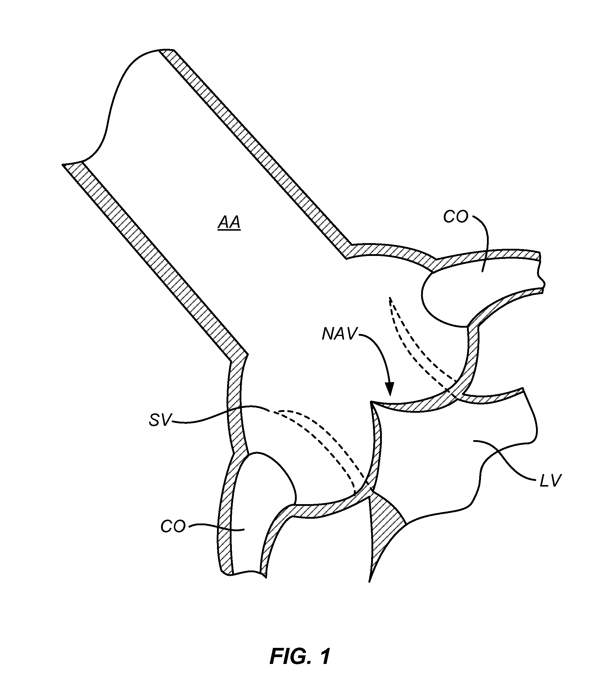
[0033]A native aortic valve (NAV) is illustrated in FIG. 1. The native aortic valve is positioned just below the ascending aorta (AA) and the Sinus of Valsalva (SV). Coronary ostia (CO) branch off from the Sinus of Valsalva and provide perfusion to coronary arteries which feed the heart muscle (not illustrated). Beneath the native aortic valve is the left ventricle, and the aortic valve is closed during diastole (as shown in full line in FIG. 1) and opens during systole (shown in broken line in FIG. 1) when the left ventricle contracts and ejects blood from the ventricle into the aorta.

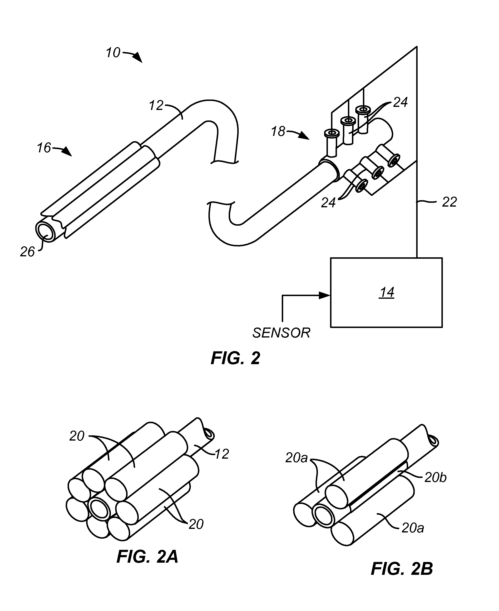
[0034]Referring to FIG. 2, a system 10 for regulating aortic regurgitation according to the present invention comprises a temporary aortic valve (TAV), catheter 12 and a controller 14. The catheter 12 has a balloon structure 16 at or near its distal end and an inflation hub 18 at or near its proximal end. In the illustrated embodiment, the balloon structure 16 includes six identical cylindrical balloo...


PUM


Abstract

Methods and systems for regulating aortic regurgitation during aortic valve replacement or repair procedures utilize a temporary aortic valve (TAV) catheter and a controller. The temporary aortic valve catheter has an expandable occlusion device which can partially occlude the aortic lumen during ventricular diastole with a lesser occlusion during ventricular systole. Exemplary balloon structures include multiple, independently inflatable balloons which are inflated in synchrony with the cardiac cycle by the controller. By controlling aortic regurgitation, the repair or replacement protocols can be conducted with less interference from blood flow.

Description

CROSS REFERENCE TO RELATED APPLICATIONS[0001]This application claims the benefit under 35 U.S.C. 119 of U.S. Provisional Patent Application No. 61 / 384,989, filed Sep. 21, 2010, the full disclosure of which is incorporated herein by reference.BACKGROUND OF THE INVENTION[0002]1. Field of the Invention[0003]The present invention relates generally to medical devices and methods. More particularly, the present invention relates to a method and system for facilitating percutaneous aortic valve replacement.[0004]Patients suffering from significant aortic valve disease are frequently treated by aortic valve replacement procedures. While most aortic valve replacements are still performed in open chest procedures, recently there have been significant advances in minimally invasive aortic valve replacement where the valve is introduced through either a transapical approach (minimally invasive) or a transvascular (percutaneous) approach over the aortic arch.[0005]Both transapical and transvascu...

Claims


Application Information

Patent Timeline
Patent Type & Authority Patents(United States)
IPC IPC(8): A61M29/00A61F2/24A61B17/12A61M25/10A61B17/00
CPCA61F2/2427A61B17/1204A61B17/12118A61B17/12136A61B2017/00703A61F2250/0059A61M25/1011
Inventor HO, PAUL C.
Owner HOCOR CARDIOVASCULAR TECH
Learn More