Magnetic recording head, magnetic head assembly, magnetic recording apparatus, and magnetic recording method

a recording head and magnetic recording technology, applied in special recording techniques, recording signal processing, instruments, etc., can solve the problems of slowing down temporarily, not being able to achieve such a high recording density, and being difficult to efficiently apply the high frequency magnetic field to the medium

Active Publication Date: 2010-06-03
KK TOSHIBA
View PDF98 Cites 123 Cited by
  • Summary
  • Abstract
  • Description
  • Claims
  • Application Information

AI Technical Summary

Benefits of technology

[0013]According to a fifth aspect of the invention, a magnetic recording apparatus includes a magnetic recording medium, a magnetic recording head, and a signal processor. The magnetic recording head includes a first magnetic pole, a second magnetic pole, a spin torque oscillator, a first coil, a and a second coil. The first magnetic pole applies a recording magnetic field to the magnetic recording medium. The second magnetic pole is provided parallel to the first magnetic pole. At least a portion of the spin torque oscillator is provided between the first magnetic pole and the second magnetic pole. The first coil magnetizes the first magnetic pole. A current is passed through the second coil independently of the first coil. The signal processor writes and reads a signal on the magnetic recording medium by using the magnetic recording head. The signal processor includes a first current circuit and a second current circuit. The first current circuit supplies a recording current to the first coil. The recording current includes a recording signal to be recorded on the magnetic recording medium. The second current circuit supplies a modulating current to the second coil. In addition, the modulating current includes either one of a signal changing at a frequency higher than that of the recording signal, and a signal having the same frequency as the recording signal to change an absolute value thereof in one cycle.
[0014]According to a sixth aspect of the invention, a magnetic recording apparatus includes a magnetic recording med

Problems solved by technology

However, since the problems of heat fluctuation of a magnetic recording medium became conspicuous in the early 2000s, the speed of the increase in recording density has slowed down temporarily.
However, it will not be easy to attain such a high recording density even employing the perpendicular magnetic recording, because the problems of heat fluctuation will sti

Method used


Image

  • Magnetic recording head, magnetic head assembly, magnetic recording apparatus, and magnetic recording method
  • Magnetic recording head, magnetic head assembly, magnetic recording apparatus, and magnetic recording method
  • Magnetic recording head, magnetic head assembly, magnetic recording apparatus, and magnetic recording method

Examples


first embodiment

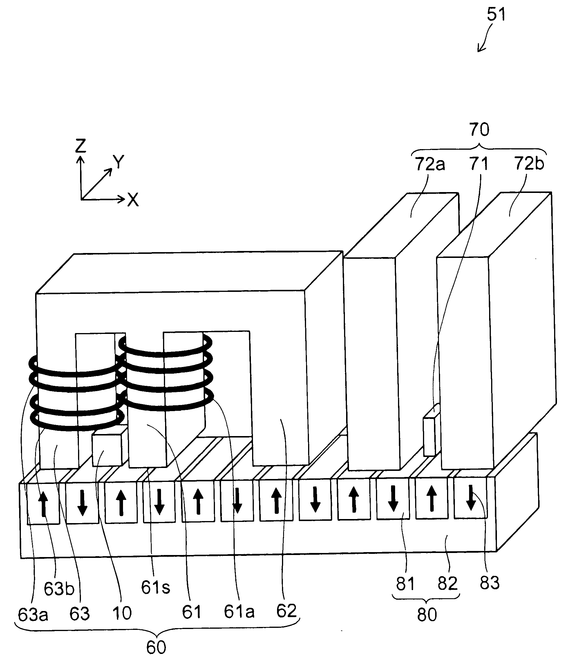
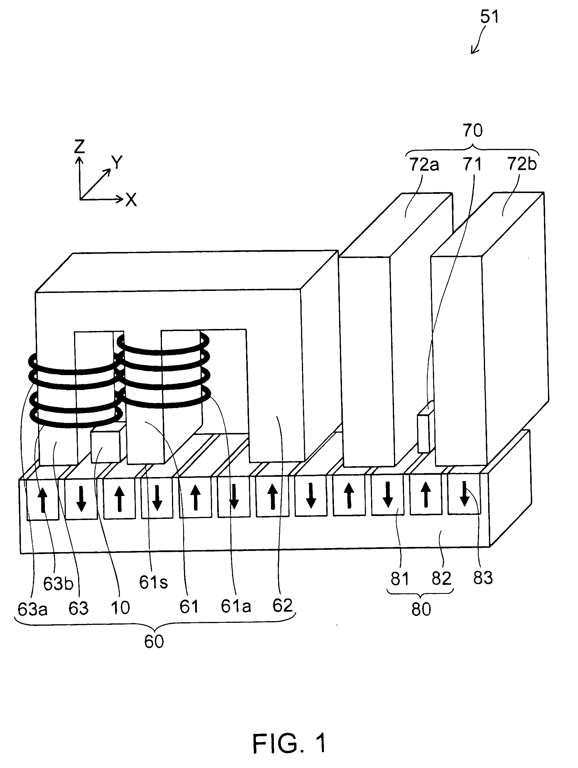
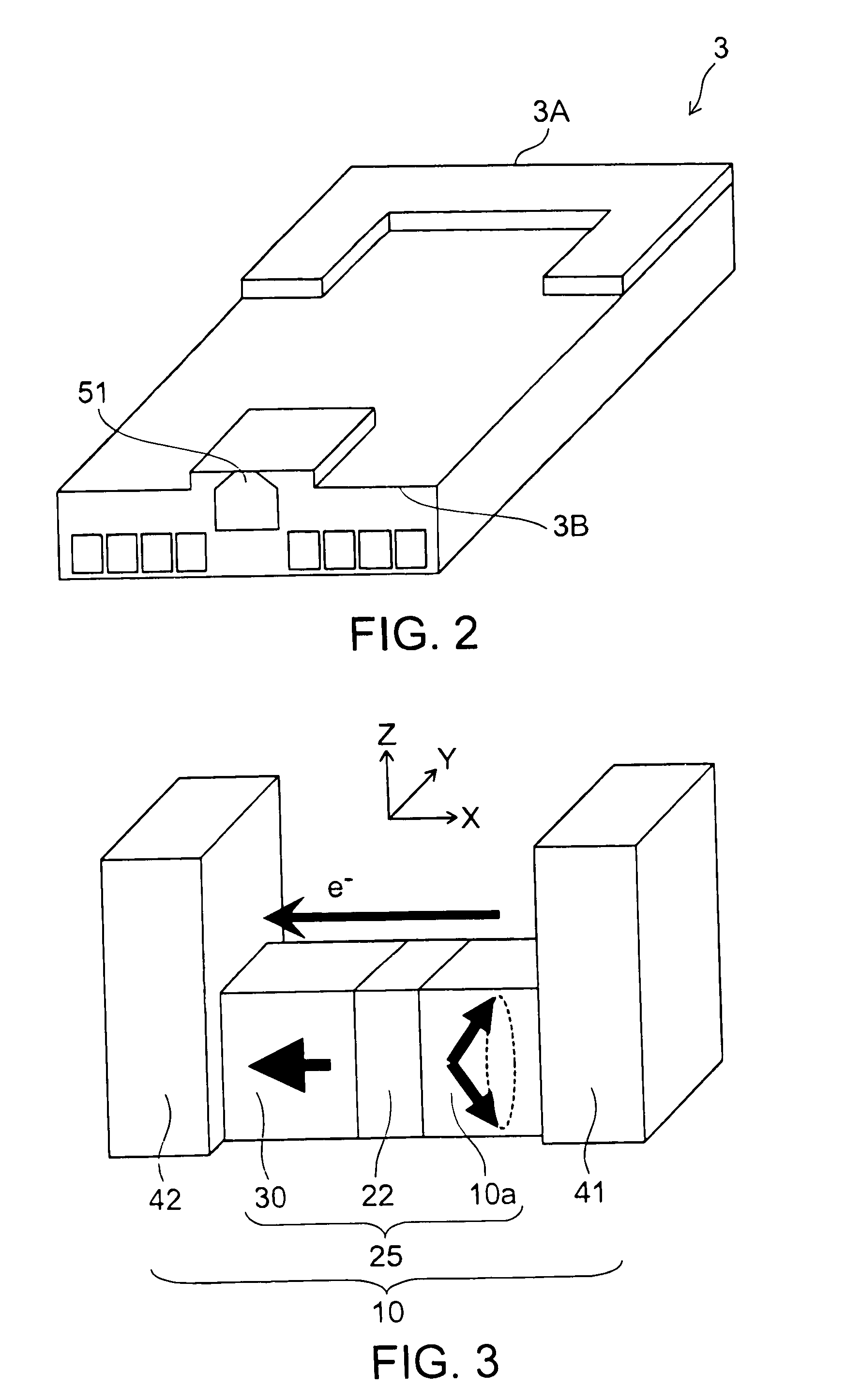
[0053]A magnetic recording head according to a first embodiment of the present invention is explained assuming that the head records on a perpendicular magnetic recording medium including magnetic grains (magnetic crystal grains). FIG. 1 is a perspective view schematically illustrating a configuration of the magnetic recording head according to the first embodiment of the invention. FIG. 2 is a perspective view schematically illustrating a configuration of a slider to carry the magnetic recording head according to the first embodiment of the invention. FIG. 3 is a perspective view schematically illustrating a configuration of a spin torque oscillator to be employed for the magnetic recording head according to the first embodiment of the invention. FIG. 4 is a perspective view schematically illustrating a configuration of a substantial portion of the magnetic recording head according to the first embodiment of the invention.

[0054]As illustrated in FIG. 1, the magnetic recording head ...

second embodiment

[0154]FIG. 16 is a perspective view schematically illustrating a structure of a substitutional portion of a magnetic recording head according to a second embodiment of the invention. As illustrated in FIG. 16, another magnetic recording head 52 according to this embodiment is not provided with the controlling magnetic pole 63, and the main magnetic pole modulation coil 61b (the modulating coil, i.e., the second coil) is mounted to the main magnetic pole 61.

[0155]The magnetic recording head 52 is provided with a main magnetic pole 61 to apply the recording magnetic field Hw to the magnetic recording medium 80, the spin torque oscillator 10 arranged together with the main magnetic pole 61, the main magnetic pole coil 61a, and the main magnetic pole modulation coil 61b capable of passing a current therethrough to magnetize the main magnetic pole 61 irrespective of the main magnetic pole coil 61a.

[0156]That is, e.g., as illustrated in FIG. 16, the main magnetic pole coil 61a is connect...

third embodiment

[0168]FIG. 18 is a perspective view schematically illustrating a structure of a substantial portion of a magnetic recording head according to a third embodiment of the invention. As illustrated in FIG. 18, another magnetic recording head 53 according to this embodiment is provided with neither the controlling magnetic pole 63 nor the main magnetic pole modulation coil 61b of the main magnetic pole 61. Then, a current with a component changing at a frequency higher than that of the recording signal Sw of the recording magnetic field Hw is being passed through the main magnetic pole coil 61a. Here, the recording magnetic field Hw records information on the magnetic recording medium 80.

[0169]The magnetic recording head 53 is provided with the main magnetic pole 61, the spin torque oscillator 10, and the main magnetic pole coil 61a. Here, the main magnetic pole 61 applies the recording magnetic field Hw to the magnetic recording medium 80. The spin torque oscillator 10 is provided to th...


PUM


Abstract

A magnetic recording head includes a first magnetic pole, a second magnetic pole, a spin torque oscillator, a first coil, a second coil, and a third coil. The first magnetic pole applies a recording magnetic field to a magnetic recording medium. The second magnetic pole is provided parallel to the first magnetic pole. At least a portion of the spin torque oscillator is provided between the first magnetic pole and the second magnetic pole. The first coil magnetizes the first magnetic pole. A current is passed through the second coil independently of the first coil. A current is passed through the third coil independently of both the first coil and the second coil.

Description

CROSS REFERENCE TO RELATED APPLICATION[0001]This application is based upon and claims the benefit of priority from the Japanese Patent Application No. 2008-305693, filed on Nov. 28, 2008, the entire contents of which are incorporated herein by reference.FIELD OF THE INVENTION[0002]The present invention relates to a magnetic recording head, a magnetic head assembly, a magnetic recording apparatus, and a magnetic recording method.DESCRIPTION OF THE BACKGROUND[0003]In the 1990s, the practical application of a MR (Magneto-Resistive effect) head and a GMR (Giant Magneto-Resistive effect) head has contributed to the skyrocketing of the recording density and capacity of an HDD (Hard Disk Drive). However, since the problems of heat fluctuation of a magnetic recording medium became conspicuous in the early 2000s, the speed of the increase in recording density has slowed down temporarily. Even so, a perpendicular magnetic recording was put in practical use in 200fifthe perpendicular magnetic ...

Claims


Application Information

Patent Timeline
IPC IPC(8): G11B5/17
CPCG11B5/1278G11B5/3123G11B5/35G11B2005/001G11B5/3133G11B20/10222G11B5/09
Inventor YAMADA, KENICHIROIWASAKI, HITOSHITAKAGISHI, MASAYUKI
Owner KK TOSHIBA
Why Eureka
Try Eureka