
Pile spin-torque oscillator with AF-mode oscillation for generating high AC-field in microwave-assisted magnetic recording

a technology of af-mode oscillation and spin-torque oscillator, which is applied in the field of perpendicular magnetic recording head, can solve the problem that a simple increase in the thickness of the fgl film cannot be considered an effective solution for increasing the ac field intensity

Active Publication Date: 2015-06-23
WESTERN DIGITAL TECH INC
View PDF20 Cites 42 Cited by
  • Summary
  • Abstract
  • Description
  • Claims
  • Application Information

AI Technical Summary

Benefits of technology

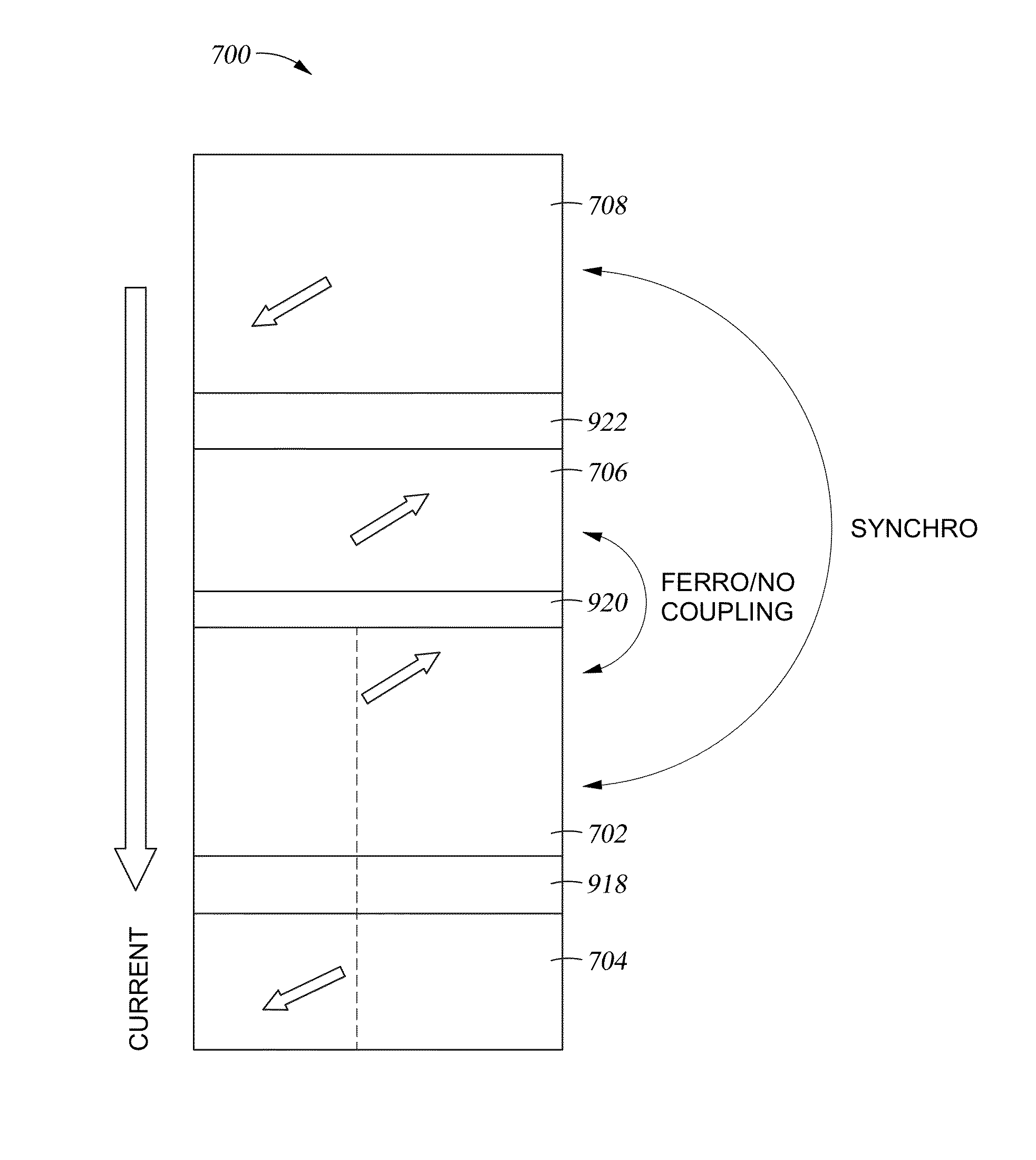
The present patent is about a structure for a perpendicular magnetic recording head used in a magnetic disk drive. It describes a microwave-assisted magnetic recording head that includes a main pole, a trailing shield, and two spin-torque oscillators. These oscillators are positioned between the main pole and the trailing shield and are separated by a spin torque shield layer. The first spin-torque oscillator has a first magnetic layer, a first non-magnetic interlayer, and a second magnetic layer. The second spin-torque oscillator has a third magnetic layer, a second non-magnetic interlayer, and a fourth magnetic layer. The applied current flows in a direction from the second magnetic layer to the first magnetic layer, and from the fourth magnetic layer to the third magnetic layer. The microwave-assisted magnetic recording head helps to improve the recording performance of magnetic disk drives.

Problems solved by technology

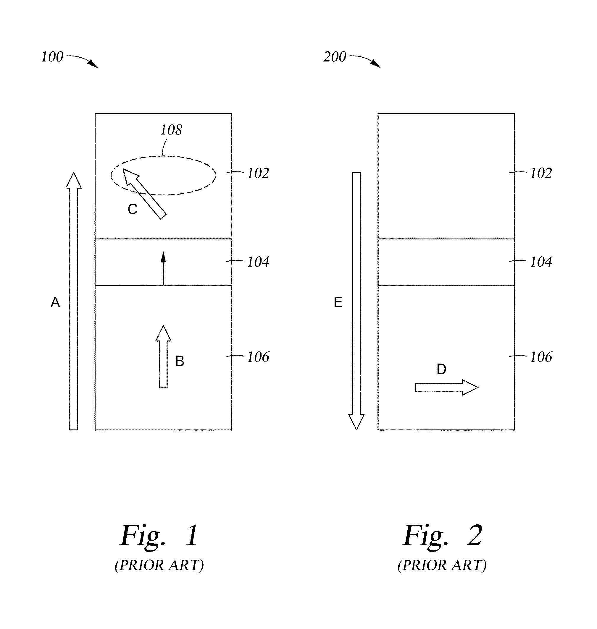
Furthermore, saturation of the AC field intensity means that the spin torque of the FGL 102 is excessively intense in the region of the spacer interface, so the FGL magnetization is disturbed and multiple magnetic domains are produced, whereas the increase in the film-plane component of the FGL magnetization is small at a position remote from the spacer interface.
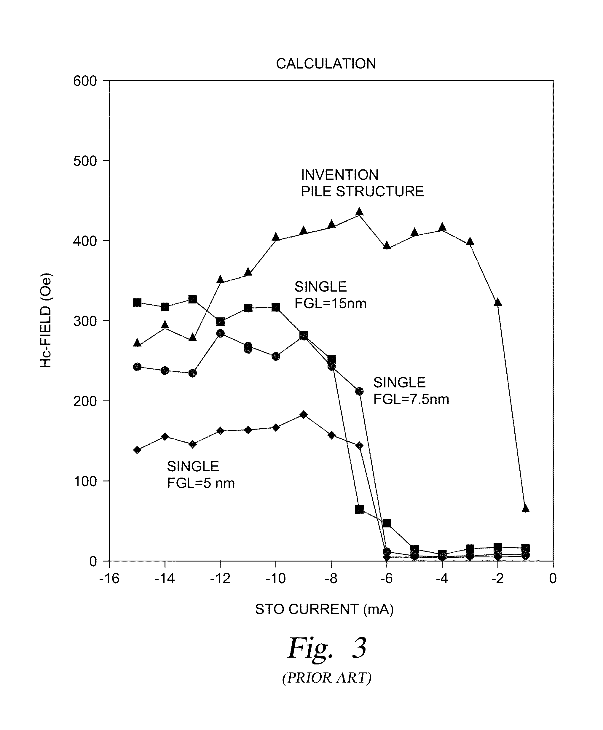
This means that a simple increase in FGL film thickness cannot be considered an effective solution for increasing the AC field intensity.

Method used


Image

  • Pile spin-torque oscillator with AF-mode oscillation for generating high AC-field in microwave-assisted magnetic recording
  • Pile spin-torque oscillator with AF-mode oscillation for generating high AC-field in microwave-assisted magnetic recording
  • Pile spin-torque oscillator with AF-mode oscillation for generating high AC-field in microwave-assisted magnetic recording

Examples


Embodiment Construction

[0025]In the following, reference is made to embodiments of the invention. However, it should be understood that the invention is not limited to specific described embodiments. Instead, any combination of the following features and elements, whether related to different embodiments or not, is contemplated to implement and practice the invention. Furthermore, although embodiments of the invention may achieve advantages over other possible solutions and / or over the prior art, whether or not a particular advantage is achieved by a given embodiment is not limiting of the invention. Thus, the following aspects, features, embodiments and advantages are merely illustrative and are not considered elements or limitations of the appended claims except where explicitly recited in a claim(s). Likewise, reference to “the invention” shall not be construed as a generalization of any inventive subject matter disclosed herein and shall not be considered to be an element or limitation of the appended...


PUM


Abstract

The present disclosure generally relates to a structure for a perpendicular microwave-assisted magnetic recording head used in a magnetic disk drive. A first spin-torque oscillator and a second spin-torque oscillator are positioned between the main pole of a recording head and a trailing shield, and are separated by a spin torque shield layer. The first spin-torque oscillator comprises a first magnetic layer, a first non-magnetic interlayer, and a second magnetic layer. The second spin-torque oscillator comprises a third magnetic layer, a second non-magnetic interlayer, and a fourth magnetic layer. An applied current is adapted to flow in a direction from the second magnetic layer to the first magnetic layer, and from the fourth magnetic layer to the third magnetic layer.

Description

BACKGROUND OF THE INVENTION[0001]1. Field of the Invention[0002]Embodiments disclosed herein generally relate to a structure for a perpendicular magnetic recording head used in a magnetic disk device.[0003]2. Description of the Related Art[0004]Investigations have been carried out in recent years into microwave-assisted magnetic recording (MAMR) as a recording method for increasing recording density. In MAMR, an AC magnetic field from a spin-torque oscillator (STO) is applied to a medium in addition to the magnetic field from a main pole. When the AC field is applied to the medium, the coercive force of the medium decreases, and high-quality recording is readily achieved. It is therefore important in MAMR to develop an STO that can generate a sufficiently large AC field. The STO 100 in FIG. 1 comprises a field generation layer (FGL) 102 for generating an AC field, an interlayer or spacer 104, and a spin polarization layer (SPL) 106 for transmitting spin-polarized torque.[0005]A mate...

Claims


Application Information

Patent Timeline
IPC IPC(8): G11B5/187
CPCG11B5/187G11B5/235G11B5/3146G11B2005/0024
Inventor SHIIMOTO, MASATOIGARASHI, MASUKAZASATO, MASASHIGE
Owner WESTERN DIGITAL TECH INC
Learn More