Magnetic recording head with protruding spin torque oscillator

a technology of spin torque oscillator and magnetic recording head, which is applied in the field of magnetic recording head and magnetic recording apparatus provided with spin torque oscillator, can solve the problems of fluctuation of magnetic recording media, difficult to achieve high recording density, and temporary slowdown of recording density

Active Publication Date: 2012-03-20
KK TOSHIBA
View PDF88 Cites 45 Cited by
  • Summary
  • Abstract
  • Description
  • Claims
  • Application Information

AI Technical Summary

Problems solved by technology

However, in the early 2000s, the problem of thermal fluctuations in magnetic recording media became manifest, and hence the increase of recording density temporarily slowed down.
However, it is considered that such a high recording density is not easy to achieve even by using perpendicular magnetic recording because the problem of thermal fluctuations becomes manifest again.
However, the technique disclosed in Patent Document 1 uses a coil to generate a high-frequency magnetic field, and it is difficult to efficiently apply a high-frequency magnetic field during high-density recording.

Method used


Image

  • Magnetic recording head with protruding spin torque oscillator
  • Magnetic recording head with protruding spin torque oscillator
  • Magnetic recording head with protruding spin torque oscillator

Examples


first embodiment

[0029]a microwave assisted magnetic recording head of the invention is described in the case of recording on a multiparticle medium for perpendicular magnetic recording.

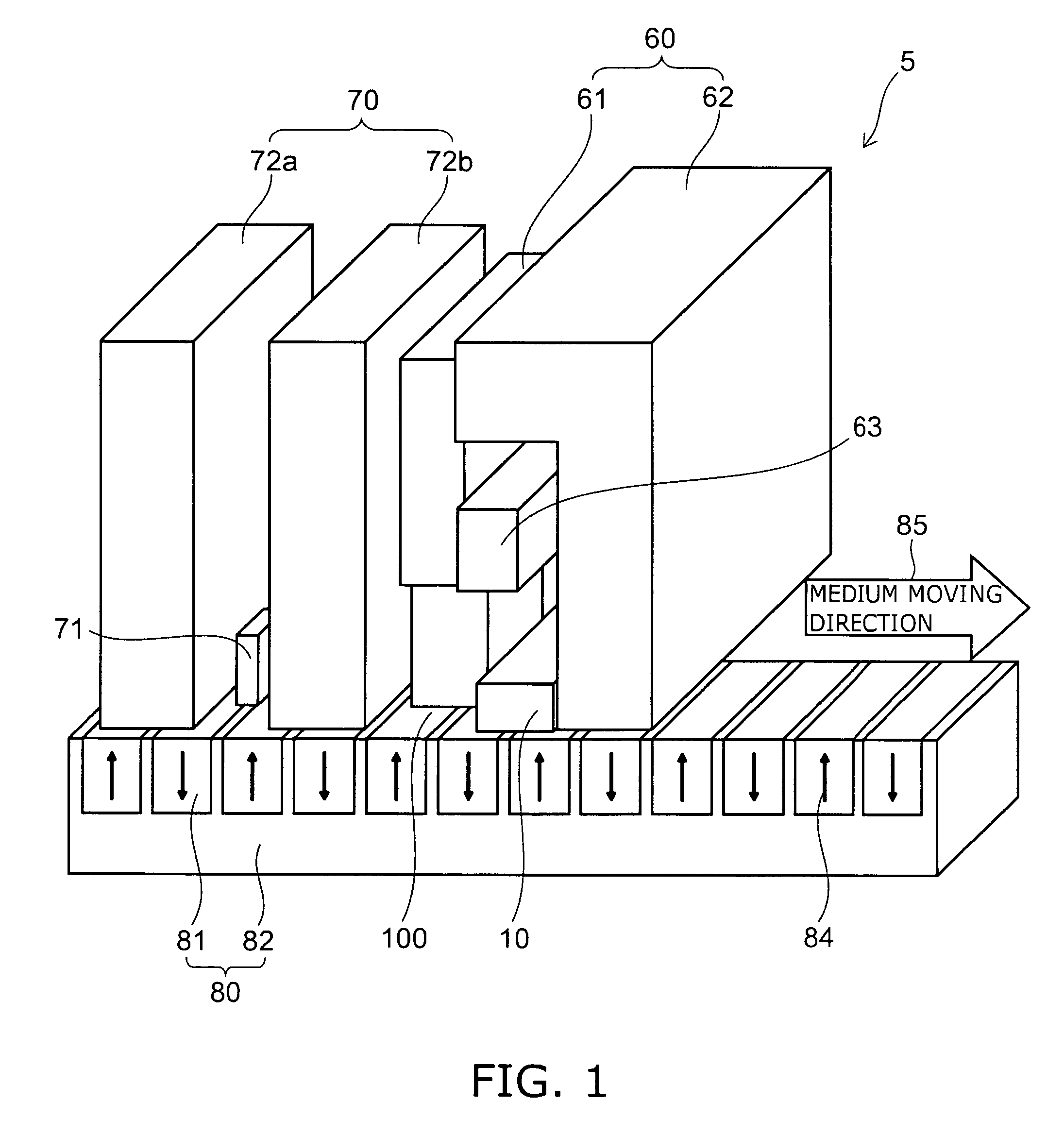
[0030]FIG. 1 is a perspective view showing the schematic configuration of a magnetic recording head according to the embodiment of the invention.

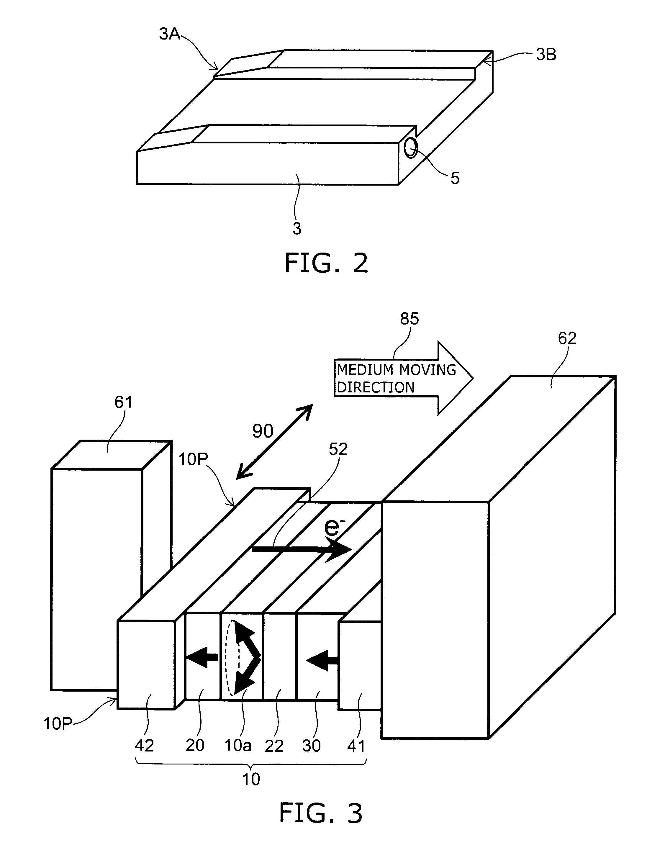
[0031]FIG. 2 is a perspective view showing a head slider on which the magnetic recording head is mounted.

[0032]The magnetic recording head 5 of this embodiment comprises a reproducing head section 70 and a writing head section 60. The reproducing head section 70 comprises a magnetic shield layer 72a, a magnetic shield layer 72b, and a magnetic reproducing device 71 provided between the magnetic shield layer 72a and the magnetic shield layer 72b.

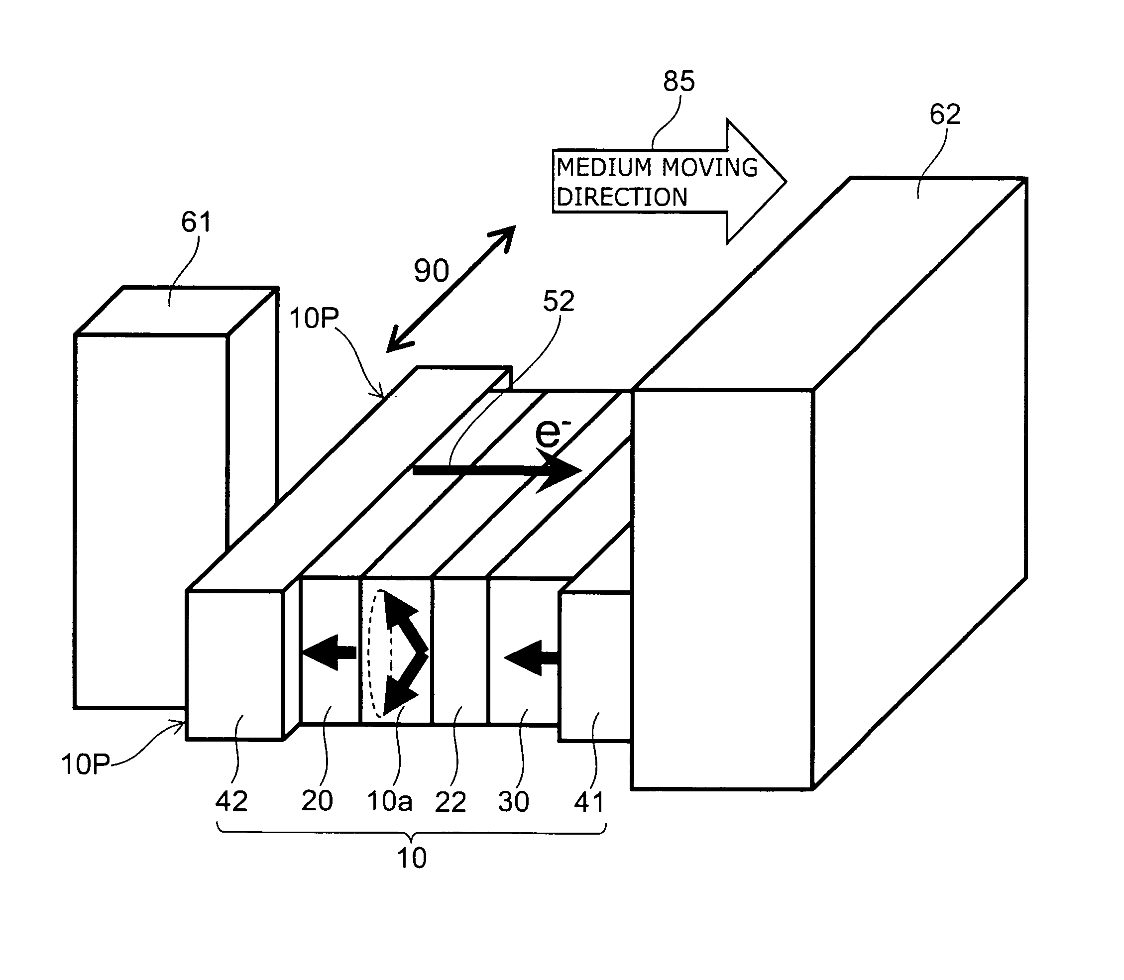
[0033]The writing head section 60 comprises a main magnetic pole 61, a return path (shield) 62, an excitation coil 63, and a spin torque oscillator 10. The components of the reproducing head section 70 and the components of the writi...

second embodiment

[0066]Next, the invention is described.

[0067]FIG. 9 is a perspective view showing the schematic configuration of a magnetic recording head 5 provided with a spin torque oscillator 10 in this embodiment.

[0068]In this embodiment, a shield 62 is placed on the trailing side of the main magnetic pole 61, and the spin torque oscillator 10 is placed between the main magnetic pole 61 and the shield 62. The spin torque oscillator 10 is laminated in the medium moving direction, and the lamination plane is parallel to the facing plane of the main magnetic pole 61 and the shield 62. In the core width direction of the main magnetic pole 61, hard films 43a (magnetic film) and 43b are provided so as to sandwich the spin torque oscillator 10. The magnetization directions of the spin injection layer 30, the oscillation layer 10a, the bias layer 20, and the hard films 43a and 43b are longitudinal and parallel to the core width direction of the main magnetic pole 61. The hard films 43a and 43b are ins...


PUM

PropertyMeasurementUnit
sizeaaaaaaaaaa
thicknessaaaaaaaaaa
thicknessaaaaaaaaaa

Abstract

A magnetic recording head includes: a main magnetic pole; a laminated body; and a pair of electrodes operable to pass a current through the laminated body. The laminated body includes a first magnetic layer, a second magnetic layer, and an intermediate layer provided between the first magnetic layer and the second magnetic layer. A lamination direction of the laminated body is substantially parallel to a medium moving direction. In a first direction parallel to an air bearing surface and perpendicular to the lamination direction, the laminated body has a protruding portion that protrudes beyond an end of a surface of the main magnetic pole facing the laminated body.

Description

CROSS-REFERENCE TO RELATED APPLICATIONS[0001]This application is based upon and claims the benefit of priority from the prior Japanese Patent Application No. 2007-229121, filed on Sep. 4, 2007; the entire contents of which are incorporated herein by reference.BACKGROUND OF THE INVENTION[0002]1. Field of the Invention[0003]This invention relates to a magnetic recording head and a magnetic recording apparatus provided with a spin torque oscillator, suitable for realizing data storage with high recording density, high recording capacity, and high data transfer rate.[0004]2. Background Art[0005]In the 1990s, the practical application of MR (magnetoresistive effect) heads and GMR (giant magnetoresistive effect) heads triggered a dramatic increase in the recording density and recording capacity of HDD (hard disk drive). However, in the early 2000s, the problem of thermal fluctuations in magnetic recording media became manifest, and hence the increase of recording density temporarily slowe...

Claims


Application Information

Patent Timeline
Patent Type & Authority Patents(United States)
IPC IPC(8): G11B5/31G11B5/235G11B5/39
CPCG11B5/02G11B5/1278G11B5/314G11B5/3153G11B2005/0002
Inventor YAMADA, KENICHIROIWASAKI, HITOSHIAKIYAMA, JUNICHITAKAGISHI, MASAYUKIFUNAYAMA, TOMOMITAKASHITA, MASAHIROSHIMIZU, MARIKO
Owner KK TOSHIBA
Why Eureka
Try Eureka