

Spin torque oscillator having multiple fixed ferromagnetic layers or multiple free ferromagnetic layers
a technology ferromagnetic layer, which is applied in the field of spin torque oscillator, can solve the problems of absorbing additional space of the torque oscillator, discharging joule heat, and creating interference with other parts of the circui
- Summary
- Abstract
- Description
- Claims
- Application Information
AI Technical Summary
Benefits of technology
Problems solved by technology
Method used
Image

Examples
first embodiment
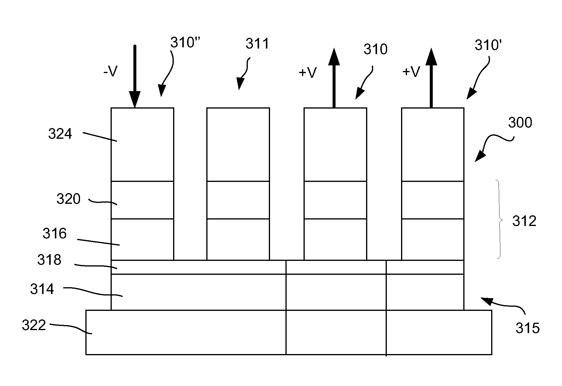
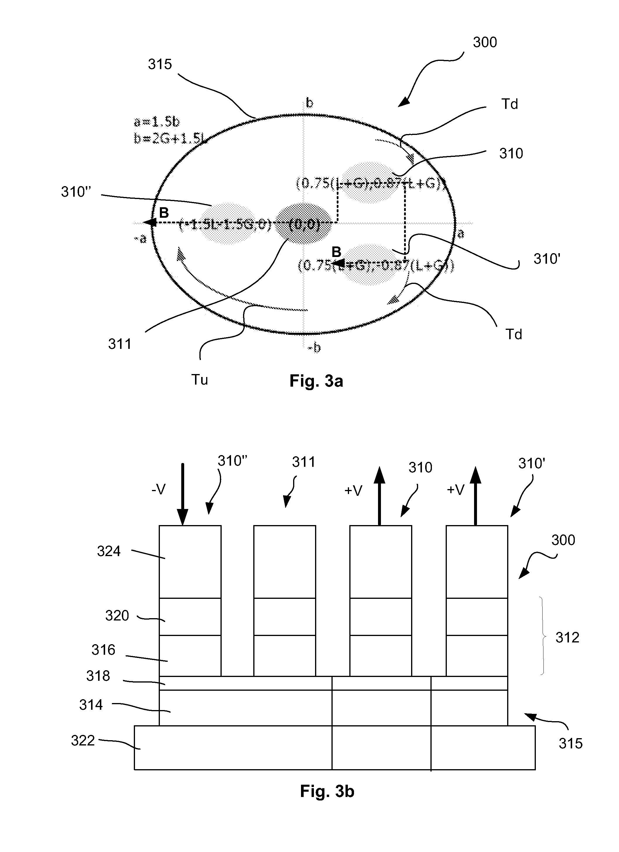
[0025]In the invention, a positioning of respective nanopillars with respect to one another may be determined as a function of the desired pattern of magnetization change within the free FM layer. As suggested above, a positioning of input nanopillars may be determined by virtue of the torque direction that they may be desired to produced within the free FM layer. In general, the output nanopillar may preferably be disposed at a location corresponding to a largest magnetization change within the free FM layer. For example, if the magnetization within the free FM layer is to move in a vortex pattern, it may be preferable to place the output nanopillar at the center of the shape defined by the top plan view of the free FM layer as the center position corresponds to a location corresponding to a largest magnetization change within the free FM layer.
[0026]According to one embodiment, as suggested for example in FIG. 3a, the input nanopillars 310, 310′ and 310″ may be disposed to surroun...
second embodiment
[0031]A simulation regarding the second embodiment as shown by way of example in FIGS. 5a and 5b has been performed. The Landau-Lifshitz-Gilbert equations for the evolution of magnetization in two free FM layers (written here in the approximation of a uniform magnetization in each layer) are:
[0032]ⅆM1ⅆt=-γ[M1×B]+αMs[M1×ⅆM1ⅆt]-γℏP2J2Ms12Ms2et1·g(θ)[M1×[M1×M2]]Eq.(9)
[0033]Where B is magnetic field equal to zero for this example, M1,2 is the magnetization in each layer, Ms1,2 is the saturation magnetization in each layer, t1,2 is the thickness of each layer, θ=θ1−θ2 is the difference of angles of magnetizations for each layer, J is the current density, P1,2 is the spin polarization of carriers for each layer. Therefore if both layers are free, the difference of the magnetization angles evolves as:
[0034]ⅆθⅆt=γℏJsinθ2eg(θ)(P2t1M1-P1t2M2)Eq.(10)
[0035]It is this difference that determines the resistance of the stack in terms of resistances of the parallel and ant...
embodiment 600
[0038]Referring next to FIG. 6, a method embodiment is depicted in flowchart format. A method embodiment 600 at block 610 includes making a spin torque oscillator configured to generate microwave electrical oscillations in the absence of two stable oscillation states and without the use of a magnetic field external thereto. Making a spin torque oscillator according to embodiments may include, as shown at block 620 providing a spin torque oscillator having a plurality of input nanopillars or it may include, as shown at block 630, providing a spin torque oscillator having a nanopillar having a plurality of free FM layers.
[0039]Referring to FIG. 7, there is illustrated one of many possible systems 900 in which embodiments of the present invention may be used. In one embodiment, the electronic arrangement 1000 may include an integrated circuit 710 including a spin torque oscillator, such as oscillator 300 or 500 of FIGS. 3a-3b or 5a-5b. Arrangement 1000 may further include a microproces...
PUM
 Abstract
Description
Claims
Application Information