Driving apparatus for a ceiling fan

a technology for driving apparatuses and ceiling fans, applied in the direction of electronic commutators, motor/generator/converter stoppers, dynamo-electric converter control, etc., can solve the problems of user danger, reduced use efficiency, and reduced use of transmission lines, so as to reduce the amount of excessively large holes opened, reduce the loss of structural integrity, and reduce the number of transmission lines used

Inactive Publication Date: 2010-02-16
RHINE ELECTRONICS
View PDF13 Cites 123 Cited by
  • Summary
  • Abstract
  • Description
  • Claims
  • Application Information

AI Technical Summary

Benefits of technology

[0011]An objective of this invention is to provide a driving apparatus for a DC brushless motor of a ceiling fan. By setting sensors and coders outside the DC brushless motor, the DC brushless motor can be driven without the need of electromagnetic sensors. In this way, the number of transmission lines that are used is reduced, thereby reducing the amount of excessively large holes opened in hardware of the motor, thus reducing the loss of structural integrity in the motor 1.
[0013]Another objective of this invention is to provide a controller that can store the rotation speed of a DC brushless motor, so that when turned off and then restarted again, the motor can resume operation at the rotation speed it possessed when it was turned off.
[0014]This invention stores the rotation speed of the motor before it was turned off by detecting a turn-off time, and has the motor reacquire this previous rotation speed when restarted, thereby eliminating the need of the round-robin switching mode.
[0015]Yet a further objective of this invention is to provide a protection circuit, which, by comparing a signal related to the rotating load of the DC brushless motor against a reference, can reduce the rotation speed of, or turn off completely, the motor in order to protect it from any damage.

Problems solved by technology

Since the electromagnetic sensors are located inside the motor, some destructive processes such as drilling are preformed on the hardware in order to route the transmission lines between the motor and the controlling circuit for transmitting output signals from the electromagnetic sensors.
Obviously, such large connection holes may compromise the integrity of the motor axle, and put the user in danger after long periods of service.
To obtain the same speed as that before it is turned off, the user has to turn on and off the motor in succession through the entire operation cycle, which is particularly inconvenient.
Further, when the fan operates under an increased load, if the controller is not provided with a protection function, the motor overheat or even fail under an unendurable load.

Method used


Image

  • Driving apparatus for a ceiling fan
  • Driving apparatus for a ceiling fan
  • Driving apparatus for a ceiling fan

Examples


Embodiment Construction

[0023]This invention relates primarily to the application of the sensing technology in the driving control of a DC brushless motor of a ceiling fan, and will be described in detail hereinafter with reference to the preferred embodiment.

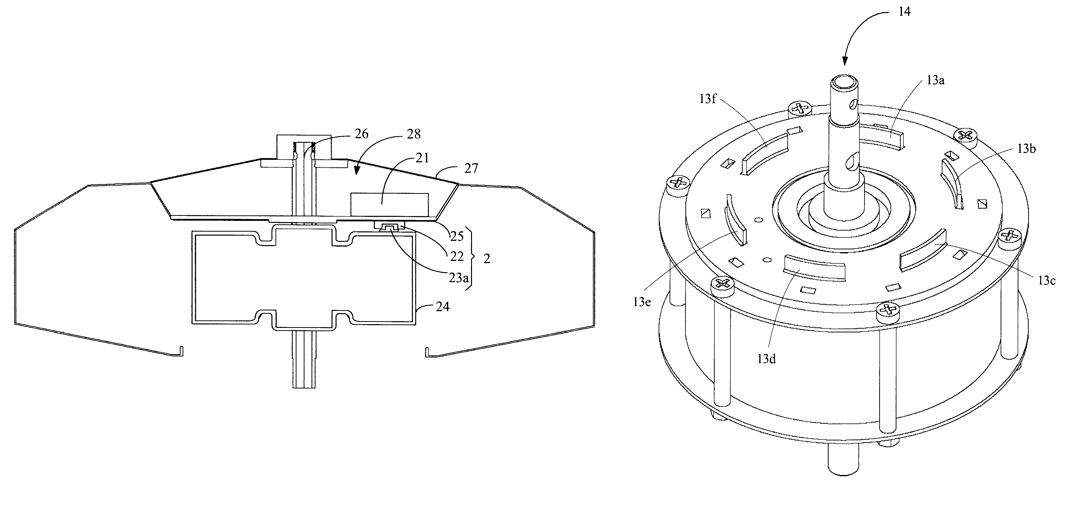
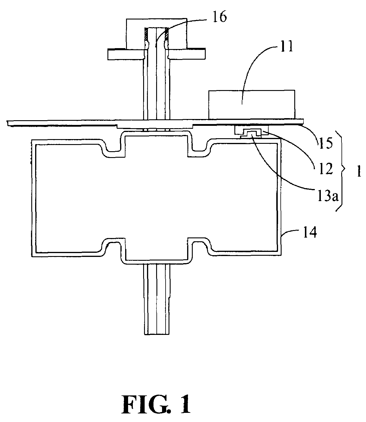
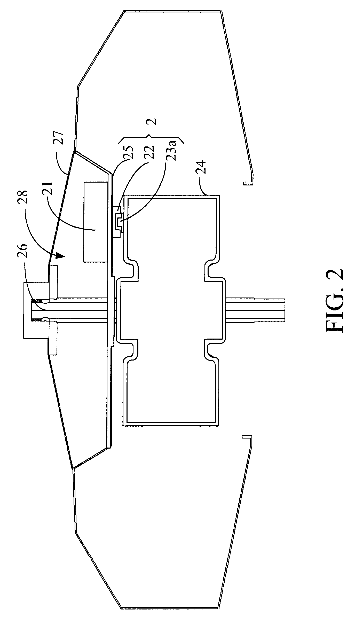
[0024]FIG. 1 depicts a schematic view of the driving apparatus 1 for the ceiling fan (not shown), the DC brushless motor 14 included in the ceiling fan, and the controller 11. The driving apparatus 1 comprises a supporting element 15, a sensor 12, and a plurality of coders 13a˜13h. For clarity, only one coder 13a is illustrated in FIG. 1. In this embodiment, the sensor 12 is an infrared ray interceptor, that is, an invisible spectrum interceptor, and the plurality of coders 13a˜13h are intercepting coders with a specific lateral dimension as shown in FIG. 3. In other embodiments, the driving apparatus may also comprise a plurality of sensors arranged corresponding to the position of the stator in order to sense the motion of the plurality of coders re...


PUM


Abstract

A driving apparatus for a DC brushless motor of a ceiling fan is provided. By setting at least one coder and one sensor outside the DC brushless motor, the driving apparatus can sense the position of magnetic poles of the motor for driving the motor. Meanwhile, a controller set with the motor stores the rotation speed of the motor before being turned off by detecting the turn-off time of a turn-on / off signal.

Description

RELATED APPLICATION[0001]This application claims the benefit of priority based on Chinese Patent Application No. 200710138661.0 filed on Jul. 19, 2007.BACKGROUND[0002]1. Field of the Invention[0003]The present invention relates to a driving apparatus for a ceiling fan; more particularly, the present invention relates to a driving apparatus for the DC brushless motor of a ceiling fan, the driving apparatus of which comprises a coder and a sensor disposed outside the DC brushless motor.[0004]2. Descriptions of the Related Art[0005]DC brushless motors have several advantages, such as high torque at low speed, low electromagnetic interference, no noise, and maintenance free of carbon brushes. However, to maintain smooth operation of a DC brushless motor, and to have it start successfully from a stationary state, electromagnetic sensors (e.g., hall sensors) have to be placed in these motors to sense the variation of the magnetic field due to positional variation of the magnetic poles rel...

Claims


Application Information

Patent Timeline
Patent Type & Authority Patents(United States)
IPC IPC(8): H02P1/18
CPCH02K11/0073H02P6/16H02K11/33
Inventor LIAO, YIN SHENG
Owner RHINE ELECTRONICS
Why Eureka
Try Eureka