

Magnetic recording head and magnetic recording apparatus
a recording head and magnetic technology, applied in the manufacture of head surfaces, special recording techniques, instruments, etc., can solve the problems of slowing down temporarily the increase of recording density, difficult to achieve high recording density, and fluctuations in magnetic recording media
- Summary
- Abstract
- Description
- Claims
- Application Information
AI Technical Summary
Problems solved by technology
Method used
Image

Examples
first embodiment
[0040]A first embodiment of a microwave assisted magnetic head of the invention is described in the case of recording on a multiparticle medium for perpendicular magnetic recording.
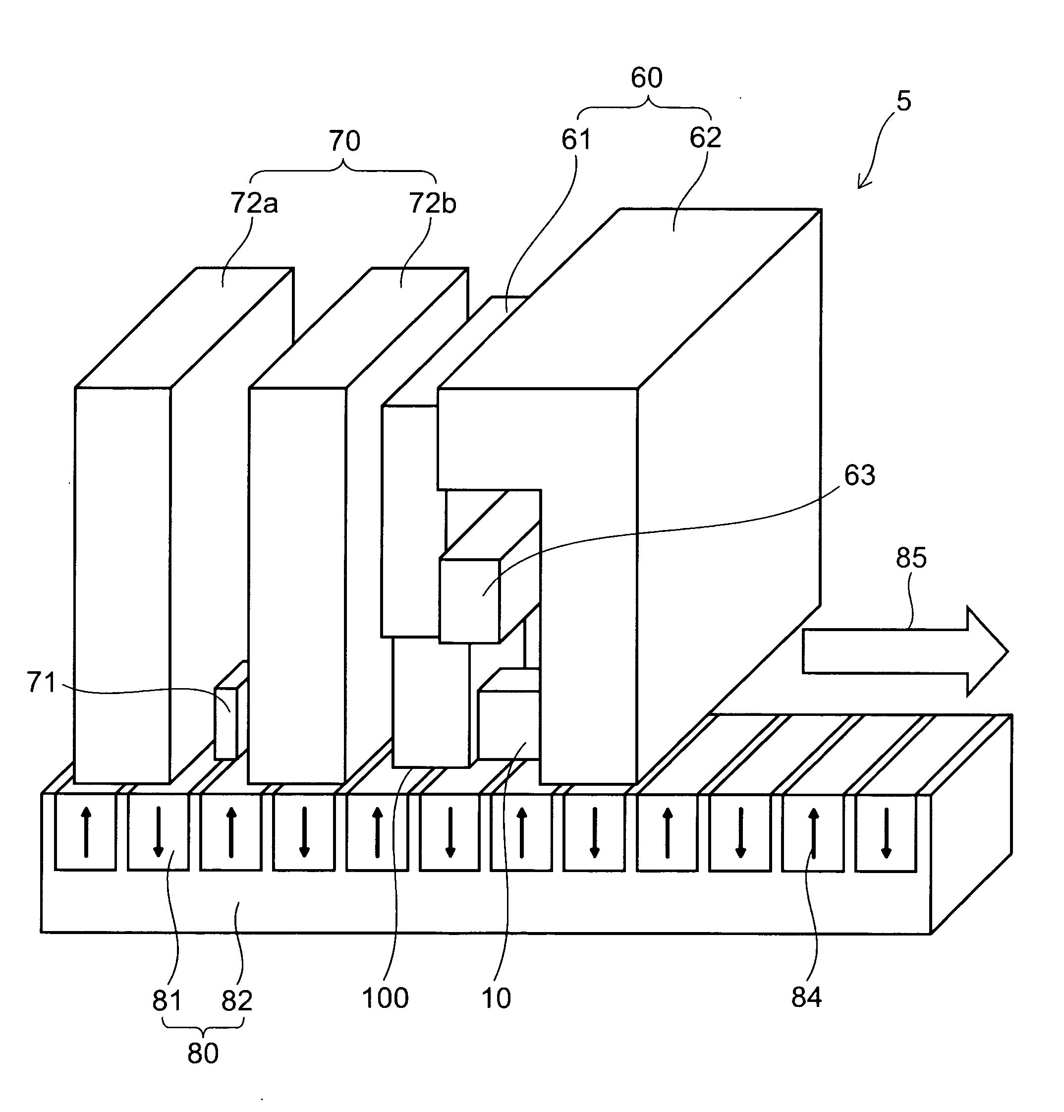
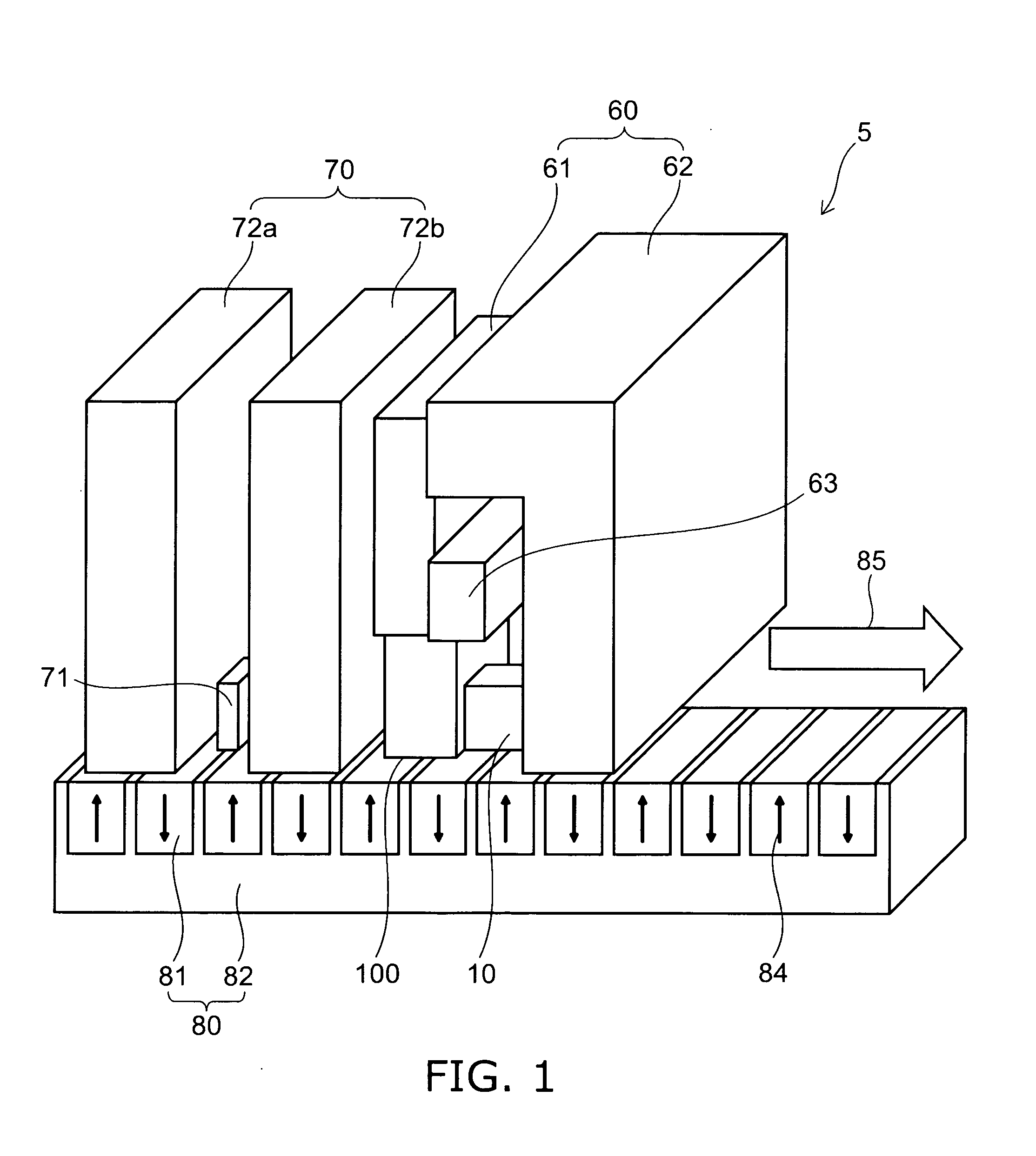
[0041]FIG. 1 is a perspective view showing the schematic configuration of a magnetic recording head 5 according to the embodiment of the invention.
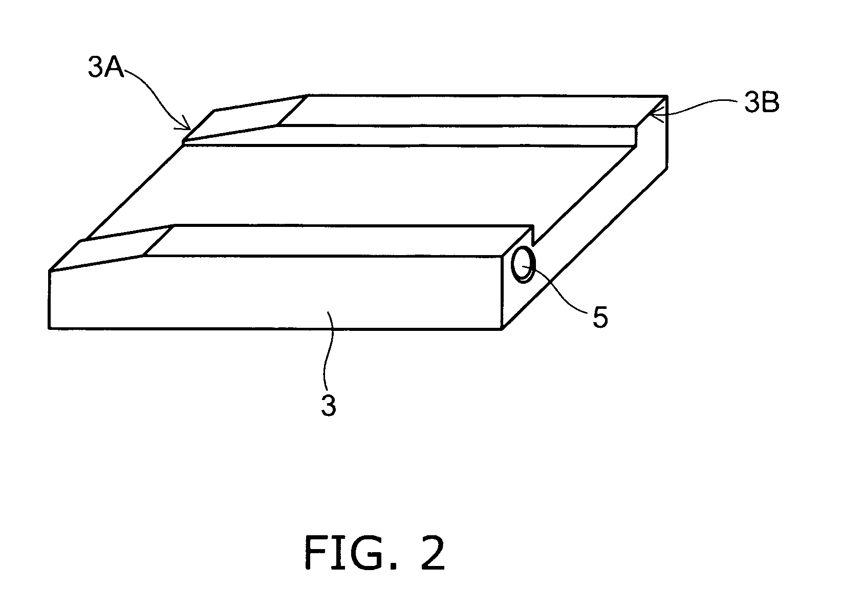
[0042]FIG. 2 is a perspective view showing a head slider on which the magnetic recording head 5 is mounted.
[0043]The magnetic recording head 5 of this embodiment comprises a reproducing head section 70 and a writing head section 60. The reproducing head section 70 comprises a magnetic shield layer 72a, a magnetic shield layer 72b, and a magnetic reproducing device 71 provided between the magnetic shield layer 72a and the magnetic shield layer 72b.
[0044]The writing head section 60 comprises a main magnetic pole 61, a return path (shield) 62, an excitation coil 63, and a spin torque oscillator 10. The components of the reproducing head section 70 and the compone...
second embodiment
[0077]Next, a second embodiment of the invention is described.
[0078]FIG. 10 is a perspective view showing the schematic configuration of a magnetic recording head 5 provided with a spin torque oscillator 10 according to the second embodiment of the invention.
[0079]In this embodiment, a shield 62 is placed on the leading side of the main magnetic pole 61, and a laminated body of the spin torque oscillator 10 is placed between the main magnetic pole 61 and the shield 62. The surface of the main magnetic pole 61 and the shield 62 opposed to the laminated body is perpendicular to the lamination direction (thickness direction of the layer) of the laminated body. The spin injection layer 30 and the oscillation layer 10a are magnetized parallel to the lamination direction, i.e., in the direction from the main magnetic pole 61 to the shield 62 or in the opposite direction.
[0080]The oscillation layer 10a includes a high-Bs soft magnetic material (FeCo / NiFe laminated film) generating a magnet...
third embodiment
[0095]Next, a third embodiment of the invention is described.
[0096]FIG. 13 is a perspective view showing the schematic configuration of a magnetic recording head 5 provided with a spin torque oscillator 10 according to the third embodiment of the invention.
[0097]In this embodiment, a shield 62 is placed on the trailing side of the main magnetic pole 61, and the spin torque oscillator 10 is provided between the main magnetic pole 61 and the shield 62. The surface of the main magnetic pole 61 and the shield 62 opposed to the laminated body is parallel to the lamination direction (thickness direction of the layer) of the spin torque oscillator 10. The spin injection layer 30 and the oscillation layer 10a are magnetized perpendicular to the lamination direction, i.e., in the direction from the main magnetic pole 61 to the shield 62 or in the opposite direction. Although the electrodes of the spin torque oscillator 10 are not shown in FIG. 13, electrodes capable of passing a current para...
PUM
 Abstract
Description
Claims
Application Information