Permanent magnet rotating machine

a permanent magnet, rotating machine technology, applied in the direction of magnetic circuit rotating parts, magnetic circuit shape/form/construction, piston pumps, etc., can solve the problems of motor performance deterioration, increased iron loss caused by harmonic components, noise and vibration, etc., to reduce the influence

Active Publication Date: 2007-06-07
AICHI ELECTRIC
View PDF17 Cites 123 Cited by
  • Summary
  • Abstract
  • Description
  • Claims
  • Application Information

AI Technical Summary

Benefits of technology

[0012] Accordingly, it is an object of the present invention to provide a technique for reducing influence caused when a rotary sh

Problems solved by technology

As a result, iron loss caused by the harmonic components increases and the motor performance is deteriorated.
Further, if the gap between the outer

Method used


Image

  • Permanent magnet rotating machine
  • Permanent magnet rotating machine
  • Permanent magnet rotating machine

Examples


first embodiment

[0074] Next, the construction of the rotor 50 of the permanent magnet motor 30 of the first embodiment will be explained in further detail with reference to FIGS. 3 and 4. FIG. 3 is a cross section of the stator 40 and the rotor 50 as viewed from the direction perpendicular to the axial direction. FIG. 4 is a cross section of the rotor 50 as viewed from the direction perpendicular to the axial direction.

[0075] In this embodiment, the rotor 50 having four poles (two pairs of poles) and the stator 40 having the construction shown in FIGS. 1 and 3 are used. This is the same with other embodiments in this invention which will be described below.

[0076] In the rotor 50, main magnetic poles and auxiliary magnetic poles alternate in the circumferential direction when viewed in cross section (perpendicular to the axial direction). Magnet insert holes are provided in the main magnetic poles.

[0077] In the following description, the main magnetic poles are represented by main magnetic poles ...

second embodiment

[0134]FIG. 5 is a cross section showing a rotor 150 of a permanent magnet motor according to a second embodiment.

[0135] A rotary shaft 160 has an outside diameter larger than the bore diameter of a rotary shaft insert hole 159 and is inserted into the rotary shaft insert hole 159.

[0136] A magnet insert hole 515a1 is provided in the main magnetic pole [a] and bow-shaped in cross section (taken in a direction perpendicular to the axial direction). The bow-like shape is formed to bulge in the radially inward direction (or to be recessed in the radially outward direction).

[0137] A permanent magnet 152a having a bow-shaped cross section is inserted into the magnet insert hole 151a1, typically by a clearance fit, such that a gap is formed between the permanent magnet 152a and the magnet insert hole 151a1.

[0138] Bridges 153a1, 153a2 are provided between outer end walls 151a2, 151a3 of the magnet insert hole 151a1 and the outer circumferential surface (150DA, 150AB in FIG. 5) of the rot...

third embodiment

[0157]FIG. 6 is a cross section showing a rotor 250 of a permanent magnet motor according to a third embodiment.

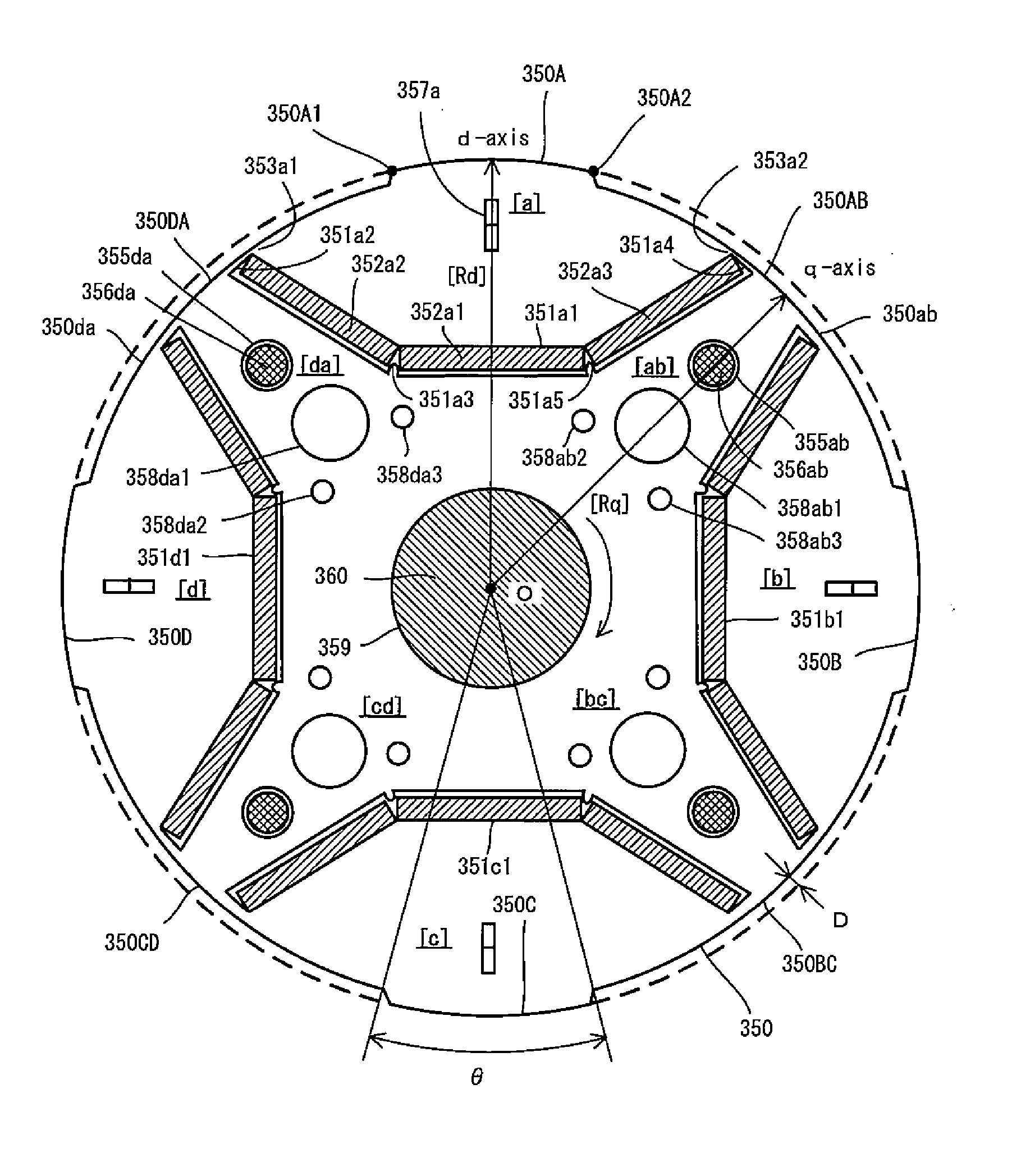
[0158] A rotary shaft 260 has an outside diameter larger than the bore diameter of a rotary shaft insert hole 259 and is inserted into the rotary shaft insert hole 259. Magnet insert holes 251a1, 251a4 are arranged in V-shape in the main magnetic pole [a] of the rotor 250. The V-shape is formed to bulge in the radially inward direction (or to be recessed in the radially outward direction) of the rotor 250. A bridge 253a1 is provided between the magnet insert holes 251a1 and 251a4 (in the central region of the main magnetic pole [a]).

[0159] Permanent magnets 252a1, 252a2 having a rectangular cross section (taken in a direction perpendicular to the axial direction) are inserted into the magnet insert holes 251a1, 251a4. Projections 251a3, 251a6 are formed on the magnet insert hole 251a1 and serve to position the permanent magnets 252a1, 252a2. Thus, spaces (non-magnetic re...


PUM


Abstract

A rotary shaft 60 having an outside diameter larger than the bore diameter of a rotary shaft insert hole 59 of a rotor 50 is inserted into the rotary shaft insert hole 59. A magnet insert hole 51a1 is provided in a main magnetic pole [a] of the rotor 50. Permanent magnets 52a1 to 52a3 are inserted into the magnet insert hole 51a1 such that a gap is formed between the permanent magnets 52a1 to 52a3 and the magnet insert hole 51a1. A semi-tubular rivet insert hole 55a and interlocks 57a1, 57a2 elongated in the radial direction of the rotor are disposed radially outward of the magnet insert hole 51a in the rotor. A semi-tubular rivet 56a is inserted into the semi-tubular rivet insert hole 55a such that a gap is formed between the semi-tubular rivet 56a and the semi-tubular rivet insert hole 55a. Passage holes 58ab, 58da are provided in the auxiliary magnetic poles [ab], [da].

Description

BACKGROUND OF THE INVENTION [0001] 1. Field of the Invention [0002] The present invention relates to a permanent magnet rotating machine including a rotor having magnet insert holes for receiving permanent magnets, and more particularly, to a technique for reducing influence caused when a rotary shaft is inserted into a rotary shaft insert hole of the rotor. [0003] 2. Description of the Related Art [0004] Generally, a permanent magnet motor having a rotor in which permanent magnets are inserted into magnet insert holes is used as a motor for driving a compressor which is installed, for example, in an air conditioner or a refrigerator. Such a permanent magnet motor is typically referred to as an “interior permanent magnet motor (IPM motor)”. [0005]FIG. 11 shows a rotor 850 of a permanent magnet motor disclosed in Japanese laid-open patent publication No. 7-236239, which is shown in cross section (taken in a direction perpendicular to the axial direction). [0006] The rotor 850 is form...

Claims


Application Information

Patent Timeline
IPC IPC(8): H02K21/12
CPCH02K1/2766H02K1/28H02K29/03
Inventor ITO, ISAOKUROKO, MASASHISUZUKI, MITSUHIROMANO, SHOJI
Owner AICHI ELECTRIC
Why Eureka
Try Eureka