
Systems and methods for directly generating a view using a layered approach

a layered approach and view technology, applied in the field of direct synthesis approach using layers, can solve the problems of large input image database, dense ibr methods, special capturing equipment,

Active Publication Date: 2005-07-14
RGT UNIV OF CALIFORNIA +1
View PDF2 Cites 215 Cited by
  • Summary
  • Abstract
  • Description
  • Claims
  • Application Information

AI Technical Summary

Benefits of technology

The patent describes a method for generating a virtual view from two images using layers. The method involves warping the images and determining a matching score for each pixel in the virtual view based on the warped input images. The best layer is determined and the color of each pixel in the virtual view is determined based on the depth of the pixel from the virtual viewpoint. The method also includes a coarse-to-fine scheme to solve the repetitive pattern problem and local depth voting to enforce scene consistency and detect occlusions. The technical effect of the patent is to provide a more efficient and accurate method for generating virtual views.

Problems solved by technology

These techniques require special capturing equipment and use a very large input image database, even for very small objects.
Dense IBR methods have the disadvantage of requiring a fairly large number of input images, high equipment complexity, and a large amount of image storage.
Traditional stereo algorithms cannot fully solve the Stereo Correspondence problem for objects of uniform color and texture because of matching ambiguity.
As a result, stereo algorithms fail to recover the accurate depth of objects in this situation.
Also, computing high-quality synthetic images using stereo-based approaches can be computationally expensive.
That is, methods using the direct-view synthesis approach can afford to make mistakes in the depth calculation at those locations where geometry is unimportant.
Thus, it is irrelevant that the stereo correspondence problem becomes difficult in those situations.
The problem consists in finding the voxel that corresponds to a physical surface.
But, like other voxel-based methods, it is computationally expensive and unlikely to compute high-quality synthetic views in real-time.

Method used


Image

  • Systems and methods for directly generating a view using a layered approach
  • Systems and methods for directly generating a view using a layered approach
  • Systems and methods for directly generating a view using a layered approach

Examples


Embodiment Construction

[0023] In the following description, for purposes of explanation, numerous specific details are set forth in order to provide a thorough understanding of the invention. It will be apparent, however, to one skilled in the art that the invention can be practiced without these specific details. In other instances, structures and devices are shown in block diagram form in order to avoid obscuring the invention.

[0024] Reference in the specification to “one embodiment” or “an embodiment” means that a particular feature, structure, or characteristic described in connection with the embodiment is included in at least one embodiment of the invention. The appearances of the phrase “in one embodiment” in various places in the specification are not necessarily all referring to the same embodiment.

[0025] Some portions of the detailed descriptions that follow are presented in terms of algorithms and symbolic representations of operations on data bits within a computer memory. These algorithmic ...


PUM


Abstract

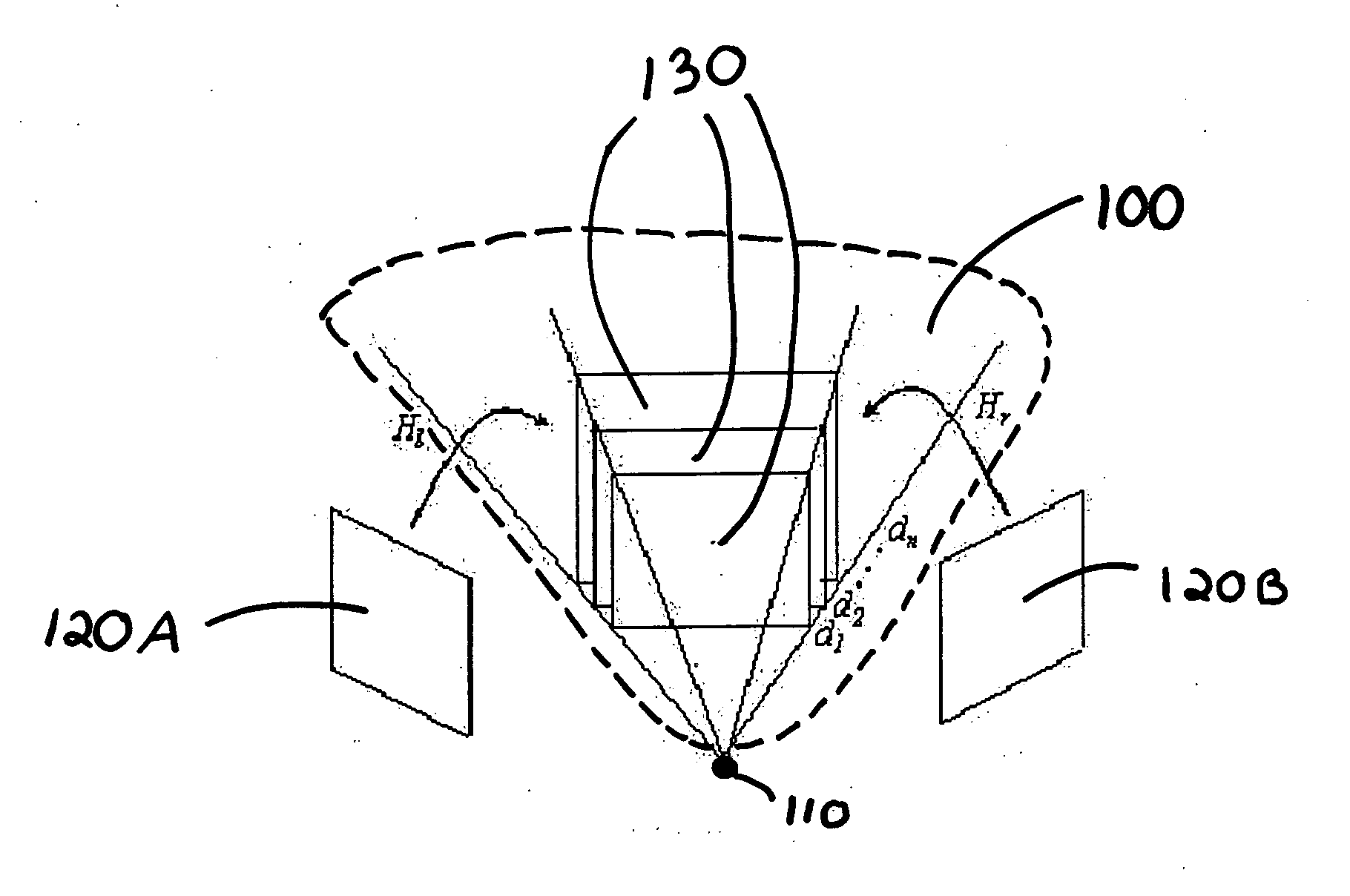
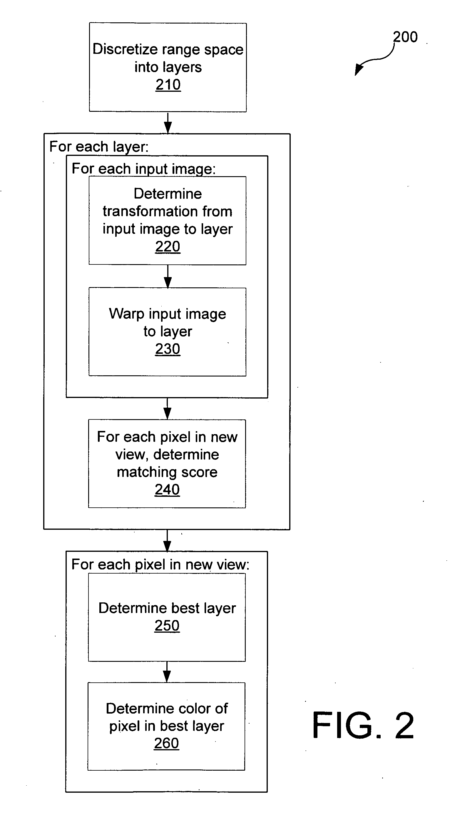
Apparatuses and methods are presented that use a direct synthesis approach using layers in order to directly generate a virtual view from a pair of images. In one embodiment, a range space is discretized into a plurality of layers. For each layer, the first input image and the second input image are warped to the layer. A matching score is then determined for each pixel in the new view based on the warped input images. For each pixel in the virtual view, a best layer is determined. After the best layer has been determined, the color of the pixel in that layer is used for that pixel in the generated view.

Description

CROSS-REFERENCE TO RELATED APPLICATION [0001] This application claims priority from the following U.S. provisional patent application, which is hereby incorporated by reference: Ser. No. 60 / 501,288, filed on Sep. 8, 2003, entitled “Sparse Image-Based Rendering Using Range Space Rendering.”BACKGROUND OF THE INVENTION [0002] 1. Field of the Invention [0003] The present invention relates to using computing devices to directly generate a virtual view of a scene. More particularly, the present invention relates to a direct synthesis approach using layers in order to directly generate a virtual view from a pair of images. [0004] 2. Description of Background Art [0005] The field of image-based rendering (IBR) covers using a set of input images of a scene from particular viewpoints to generate a new (synthetic) image of the scene from a new viewpoint. IBR techniques can be classified based on how a scene's geometry is used and represented. At one end of the spectrum, there are techniques th...

Claims


Application Information

Patent Timeline
Patent Type & Authority Applications(United States)
IPC IPC(8): G06TG06T3/00G06T15/00
CPCG06T3/0068G06T3/14
Inventor GONZALEZ-BANOS, HECTOR H.TAO, HAIKONG, DAN
Owner RGT UNIV OF CALIFORNIA
Learn More