Blind rivet and method to make same

a blind rivet and rivet body technology, applied in the field of improved blind rivets, can solve the problems of complex manufacturing process required to form the slots in the shank of the rivet body, requiring a special skill, and subject to rapid wear, and conventional rivets having preformed slots are relatively expensiv

Inactive Publication Date: 2005-07-14
NEWFREY
View PDF34 Cites 2 Cited by
  • Summary
  • Abstract
  • Description
  • Claims
  • Application Information

AI Technical Summary

Benefits of technology

[0014] Usually, the axial inner end of at least one of the plurality of slots will be radially inclined so that the at least one slot is longer where it is adjacent to and intersects the inner surface of the shank, as opposed to a shorter length where the slot engages and is adjacent to the outer surface of the shank.

Problems solved by technology

However, one of the disadvantages of peel-type blind rivets employing preformed slots is the complex manufacturing process required to form the slots in the shank of the rivet body requiring a specialised punch, usually comprising a cylindrical main body for receipt within the hollow rivet body and having four cutting arms extending radially outwards of this main body portion for cutting through the rivet shank to form the slots having substantially parallel sides.
Since the width of the slots is relatively narrow, the corresponding cutting blades from the punch must also be relatively narrow and thus are subject to rapid wear due to the high forces exerted on these cutting blades.
As such, conventional rivets having preformed slots are relatively expensive due to the associated costs of both manufacturing the complex punches and their high wear and failure rate.

Method used


Image

  • Blind rivet and method to make same
  • Blind rivet and method to make same
  • Blind rivet and method to make same

Examples


Embodiment Construction

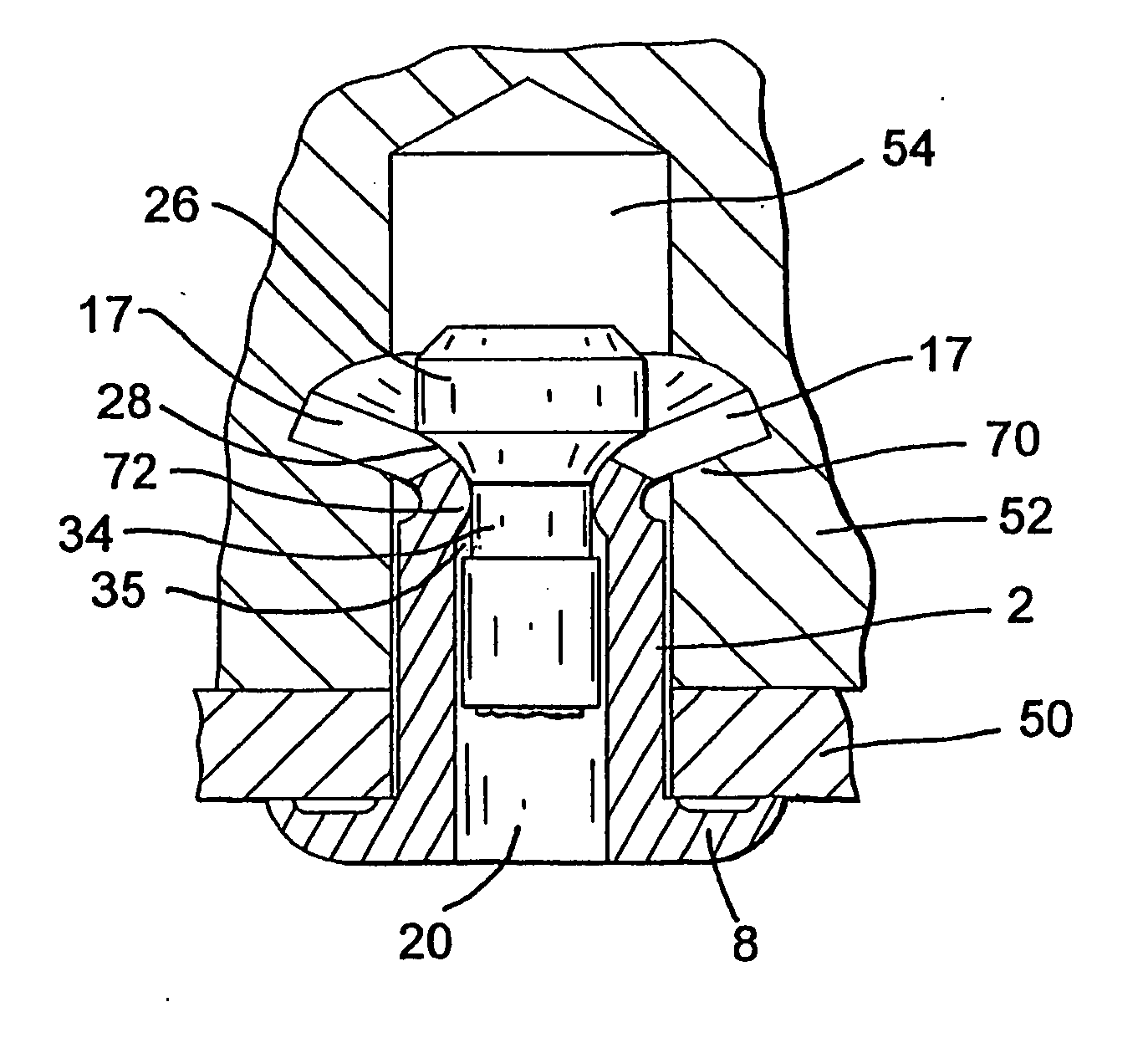
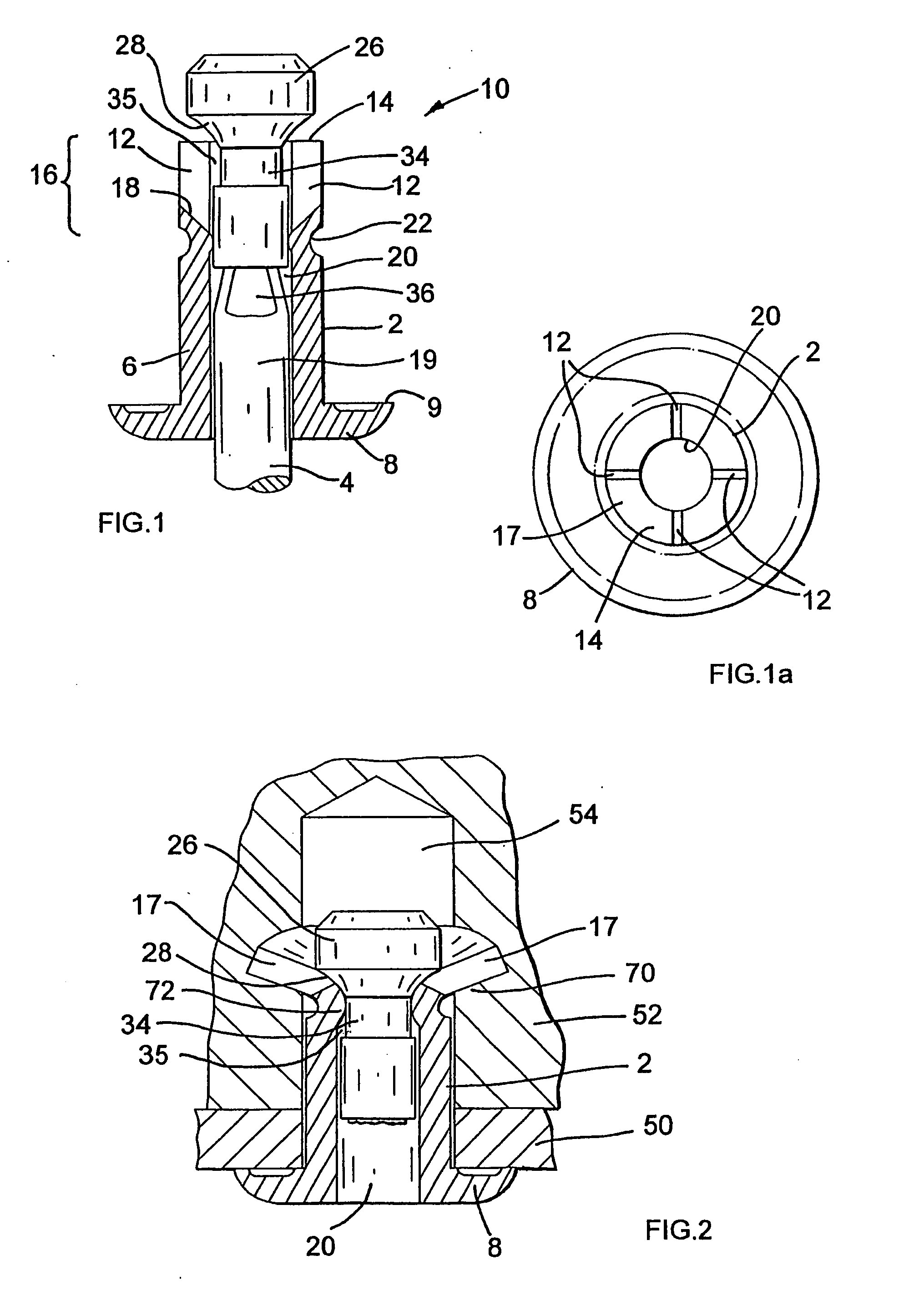
[0037] A peel-type blind rivet assembly (10), according to the prior art, is seen in FIG. 1. This blind rivet assembly (10) comprises a tubular body (2) containing a mandrel (4), and having a head (8) formed by a flattened flange portion, presenting a circumferential shoulder (9) for engagement with a first workpiece. Four equally spaced elongate slots (12) are provided in the end (14) of the shank (6) remote from the head (8) and provide an expandable portion (16) of the shank, dividing this expandable end portion into four distinct legs (17) therebetween. The base (18) of each slot (longitudinally remote from an end (14) of the shank) is axially inclined relative to an axis of the shank such that the length of the slot is longer where it is adjacent to the inner surface of the body (adjacent to the bore (20)) and is of a shorter longitudinal length where it is adjacent to the outer surface of the body.

[0038] The mandrel (4) is of conventional design comprising a head (26) having ...


PUM

PropertyMeasurementUnit
external diameteraaaaaaaaaa
internal diameteraaaaaaaaaa
widthaaaaaaaaaa

Abstract

The invention is directed to a peel-type blind rivet assembly (110) for setting in relatively soft material and comprising an elongate tubular body (102) having a shank (106) with an enlarged head (108). A free end (114) of the shank, remote from the head (108), has an expandable portion formed by a plurality of slots (112) extending partway along the shank from this remote end (114). A mandrel (104) has a stem, and a mandrel head (126) with a maximum external diameter greater than the internal diameter of the body (102), wherein at least one of the plurality of slots (112) increases in width as it extends from an outer surface of the shank towards an inner surface of the shank. There is also provided a punch (280) for forming the tapered slots (112) in the rivet body, comprising an elongate solid body having a polygonal cross section wherein at least one convergence zone formed on an end face of the punch by the tapering convergence of two adjacent side walls forms a slot cutting element (285).

Description

BACKGROUND OF THE INVENTION [0001] The present invention relates to an improved blind rivet, more particularly to a peel-type blind rivet which is particularly suitable for anchoring in relatively soft materials such as wood or plastics. [0002] Conventional blind riveting techniques which are normally used to secure together two or more workpieces, utilise a blind rivet having a tubular shank with an enlarged head at the operative end thereof such that the shank can pass through a preformed hole in extending between two workpieces, whereby a mandrel disposed within the tubular rivet body having an enlarged head is then used to compress the rivet body on the blind side (ie. behind the workpieces to be set) to create a bulge which will compress the workpieces against the enlarged head. [0003] However, where the blind side workpiece material is both of substantial thickness and is relatively soft, modified peel-type blind rivets have been employed which operate in a significantly diffe...

Claims


Application Information

Patent Timeline
Patent Type & Authority Applications(United States)
IPC IPC(8): B21K1/60B23D21/02F16B19/10
CPCB21K1/60F16B19/1054B23D21/02
Inventor JONES, STEVEN VICTOR
Owner NEWFREY
Why Eureka
Try Eureka