Clip

a technology of clips and clips, applied in the field of clips, can solve the problems of complicated operation of the reuse of the to be mounted parts, and achieve the effect of avoiding the need for a new mounting member

Inactive Publication Date: 2005-07-21
PIOLAX CO LTD
View PDF3 Cites 56 Cited by
  • Summary
  • Abstract
  • Description
  • Claims
  • Application Information

AI Technical Summary

Benefits of technology

[0008] It is an object of the present invention to provide a clip capable of being mounted integrally with a fixing member with reliability when the fixing member is inserted and fixed in a mounting hole of a to-be-fixe

Problems solved by technology

Reuse of the to be mounted member requires complicated operations

Method used


Image

  • Clip
  • Clip
  • Clip

Examples


Embodiment Construction

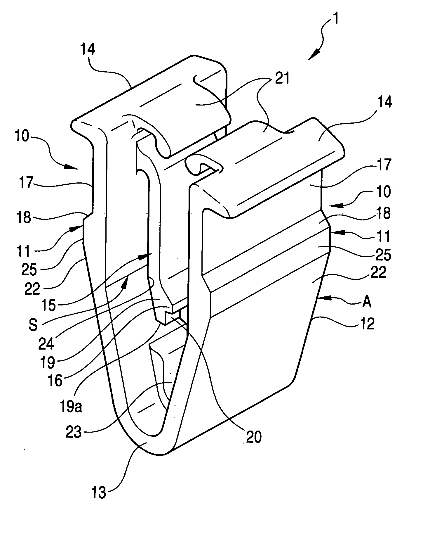
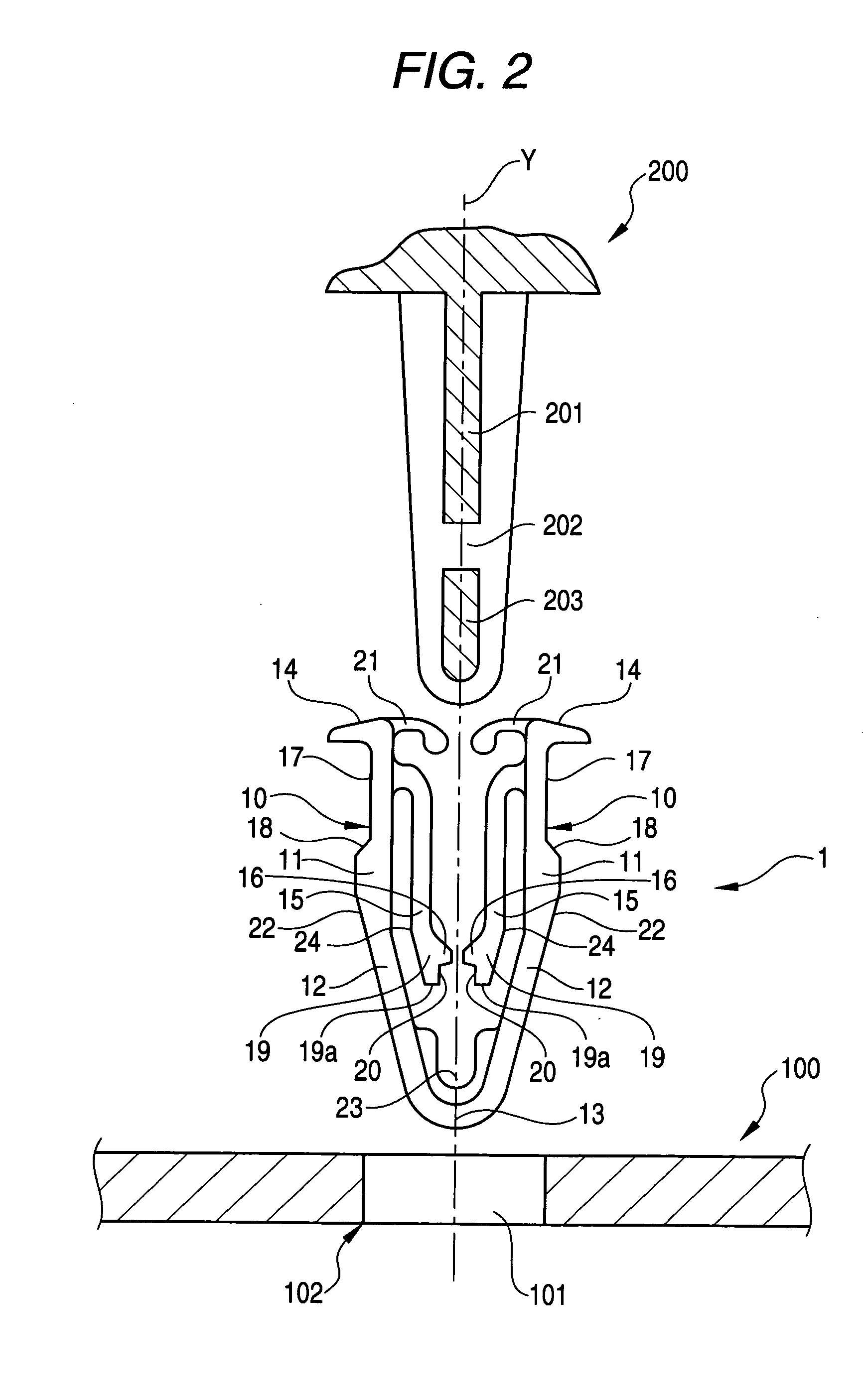
[0043]FIG. 1 is a perspective view of a clip in accordance with a first example of the present invention. FIG. 2 is an explanatory layout diagram showing the positional relationship among the clip shown in FIG. 1, a fixing member, and a to-be-fixed member prior to the fixed state. FIG. 3 is a longitudinal sectional view of the clip shown in FIGS. 1 and 2 in the fixed state. FIG. 4 is a longitudinal sectional view of the clip shown in FIG. 3 in the process of being press inserted to or pulled out from a mounting hole of the to-be-fixed member. FIG. 5 is a longitudinal sectional view of a clip in accordance with a second example of the invention in the fixed state. FIG. 6 is a longitudinal sectional view of the clip shown in FIG. 5 in the process of being press inserted to or pulled out from the mounting hole of the to-be-fixed member. FIG. 7 is a longitudinal sectional view of a clip in accordance with a third example of the invention in the fixed state. FIG. 8 is a longitudinal sect...


PUM


Abstract

A clip has a base A having a U shape composed of a pair of parallel sections, and a joining section having flexibility and interconnecting the lower parts thereof, elastic pieces respectively branching from the insides of the parallel sections in the opposed directions, and extending along the parallel sections and the joining section, claws respectively protruding inwardly on the elastic pieces, and step sections having upper surfaces respectively projecting outward from the outer sides of the parallel sections and being inclined obliquely downward.

Description

BACKGROUND OF THE INVENTION [0001] 1. Field of the Invention [0002] The present invention relates to a clip capable of mounting, to a plate-like to-be-fixed member such as a panel which has been previously provided with a mounting hole, a fixing member such as a dashboard or a switchboard including a protrusion to be inserted into the mounting hole, and being subjected to reuse after removal from the to-be-fixed member together with the fixing member. [0003] 2. Description of the Related Art [0004] Conventionally, in order to fix a to-be-mounted member including a mounting hole and a fixing member including a plate-like protrusion, a clip interposes the plate-like protrusion from the upper part in the inside of a generally U shape. The parallel sections of the U shape having an elastic function are each provided on the outer side with a step section for being locked in the hole edge of the mounting hole. Thus, the clip fixes the fixing member into the mounting hole provided in the t...

Claims


Application Information

Patent Timeline
IPC IPC(8): B60R13/02E04F19/00B60J5/00F16B5/06F16B19/00F16B21/07
CPCB60R13/0206B60R13/0256E04F19/00F16B5/065Y10T24/42F16B5/0664F16B21/075Y10T24/309F16B5/0657
Inventor ASANO, KAZUNORISHINOZAKI, NOBUYAOKADA, SHIGEO
Owner PIOLAX CO LTD
Why Eureka
Try Eureka