
Data storage device

a data storage and data technology, applied in the field of data storage devices, can solve the problems of large devices, large storage space, and large storage space of known non-volatile memory devices,

Inactive Publication Date: 2005-07-21
HEWLETT PACKARD DEV CO LP
View PDF8 Cites 20 Cited by
  • Summary
  • Abstract
  • Description
  • Claims
  • Application Information

AI Technical Summary

Benefits of technology

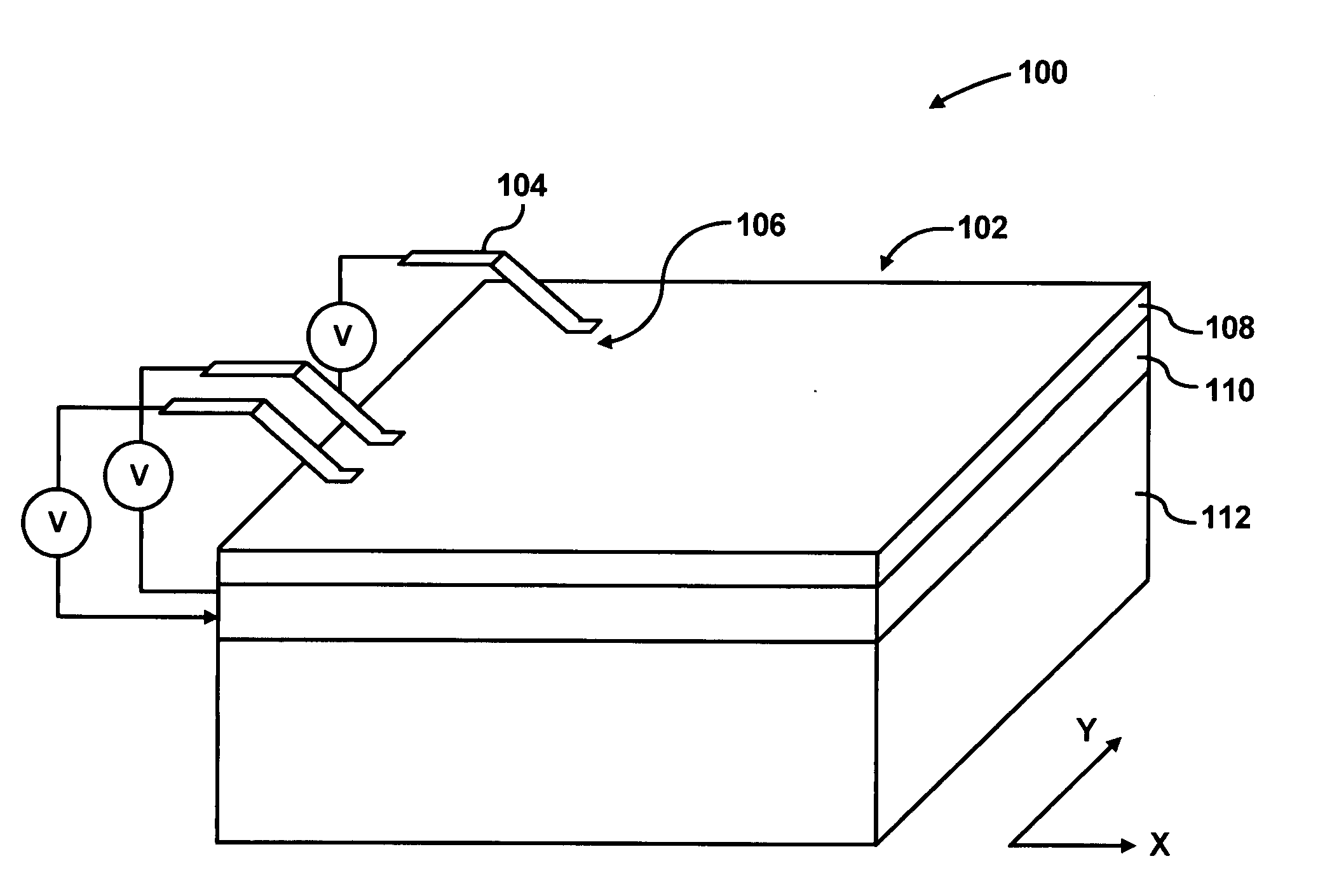
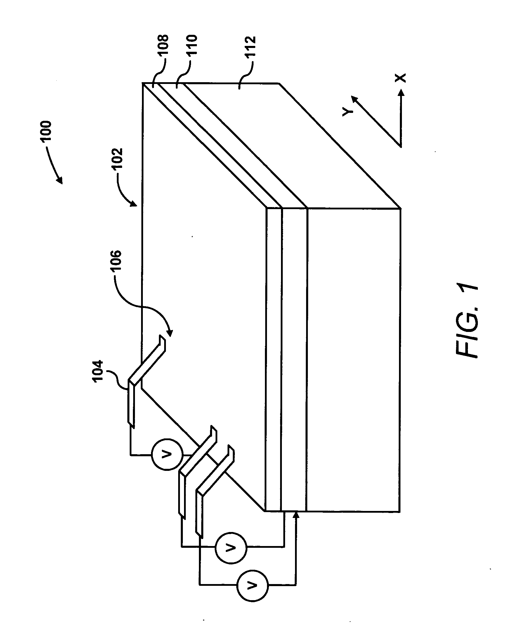
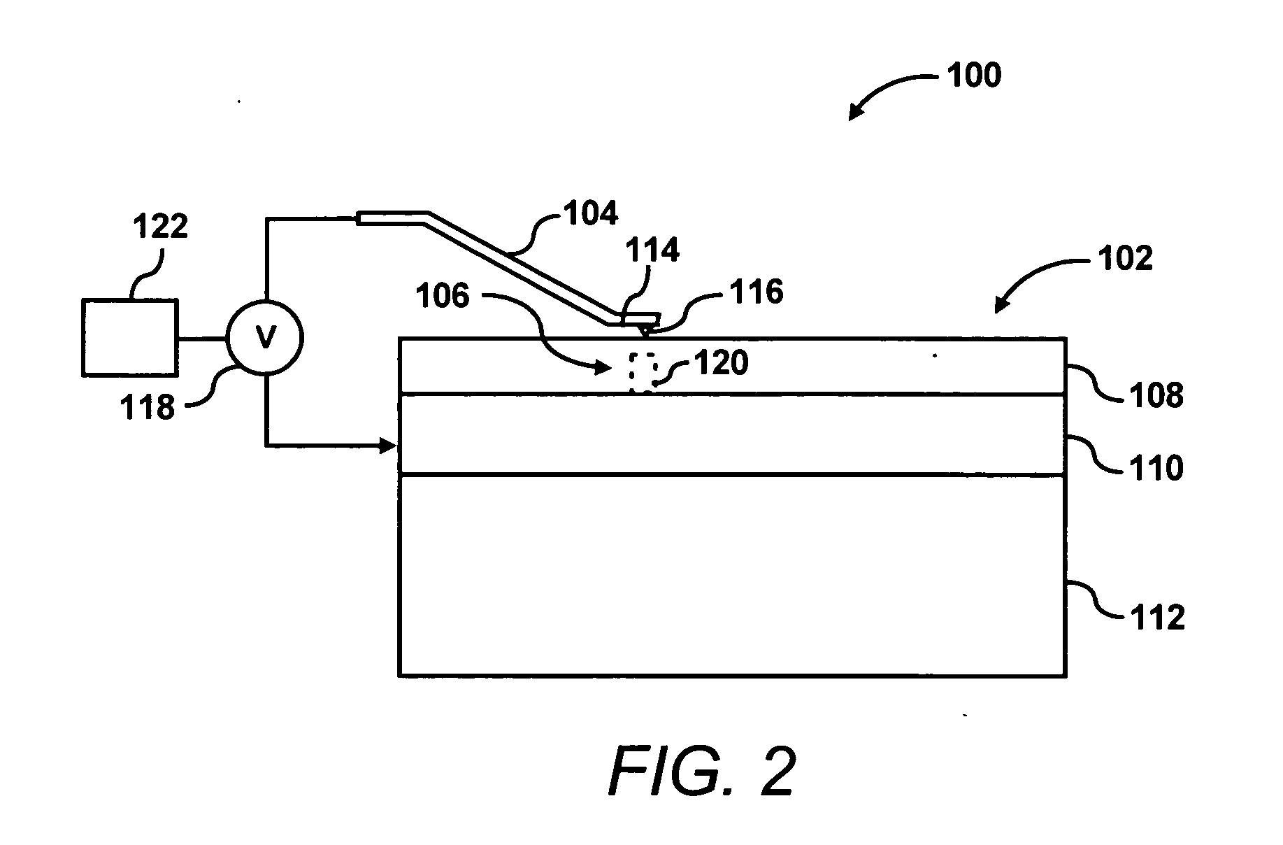
The present invention is about a data storage device that includes a storage medium with an electrode and an electrolyte layer. It also has a probe that contacts the electrolyte layer. The device has a voltage supply device that supplies voltage through the probe and electrode to create a circuit. The level of voltage determines the type of operation that can be performed on the storage medium's memory cells. The technical effect of this invention is to provide a reliable and efficient data storage device that can perform various operations on its memory cells.

Problems solved by technology

In volatile memory devices, the stored data or information is lost once the power source is disconnected.
Non-volatile memory devices may be preferable over volatile memory devices due in part to their ability to retain stored data or information in the absence of power; however, known non-volatile memory devices suffer from certain drawbacks.
For instance, the devices cited above are typically relatively large, are shock / vibration-sensitive, require relatively expensive mechanisms, and consume relatively large amounts of power.
These negative aspects typically make these memory devices non-ideal for low-power portable applications such as cell phones, palm-top computers and personal digital assistants (“PDAs”).
Although FLASH based memory devices are typically relatively small, they are somewhat limited in capacity because semiconductor lithographic processes are used to define the memory cells contained in these devices.
These memories are somewhat difficult to fabricate and have limitations in data rates and signal to noise (S / N) ratios.
This proposition may be associated with high fabrication costs due to the use of lithographic processes to realize reasonable storage densities.
Incorporation of these components typically adds to the costs and difficulties associated with fabricating PMC memories.

Method used


Image

  • Data storage device
  • Data storage device
  • Data storage device

Examples


Embodiment Construction

[0013] For simplicity and illustrative purposes, the present invention is described by referring mainly to an exemplary embodiment thereof. In the following description, numerous specific details are set forth in order to provide a thorough understanding of the present invention. It will be apparent however, to one of ordinary skill in the art, that the present invention may be practiced without limitation to these specific details. In other instances, well-known methods and structures have not been described in detail so as not to unnecessarily obscure the present invention.

[0014] A high-density storage device is provided for use in various electronic devices, for instance, computers, cell phones, lap-tops, PDAs, etc. The storage device includes a conductive probe operable to write information bits onto a storage medium, and operable to read information from the storage medium. The conductive probe is also operable to erase information from the storage medium. The writing, reading...


PUM

PropertyMeasurementUnit
thicknessaaaaaaaaaa
thicknessaaaaaaaaaa
voltageaaaaaaaaaa

Abstract

The present invention pertains to a data storage device. The data storage device includes a storage medium having an electrode and an electrolyte layer positioned on the electrode. The data storage device also includes at least one probe configured to contact the electrolyte layer. In addition, the storage medium includes a voltage supply device configured to supply voltage through the at least one probe and the electrode to thereby create a circuit between the at least one probe and the electrode. The level of voltage supplied through the at least one probe allows at least one of writing, reading, and erasing operations on the one or more memory cells of the storage medium.

Description

BACKGROUND OF THE INVENTION [0001] Memory devices are typically used in various electronic devices, for instance, computers and personal digital assistants. These memory devices may be characterized into various groups. Volatile memory devices comprise one of these groups. In volatile memory devices, the stored data or information is lost once the power source is disconnected. Examples of volatile memory devices are random access memory (“RAM”), dynamic RAM, and static RAM. In each of these types of memory devices, information is only retained so long as power is supplied to the devices. [0002] Non-volatile memory devices comprise another group of memory devices. In non-volatile memory devices, data or information is retained in the memory device even when power is shut off. Examples of non-volatile memory devices include CD-ROMs and magnetic storage devices. Non-volatile memory devices may be preferable over volatile memory devices due in part to their ability to retain stored data...

Claims


Application Information

Patent Timeline
Patent Type & Authority Applications(United States)
IPC IPC(8): G11B9/00G11B9/04G11B9/14G11B21/02G11C11/21G11C13/02G11C16/02H01L29/00
CPCB82Y10/00G11C13/0011G11B9/04
Inventor LAM, SI-TYNABERHUIS, STEVE
Owner HEWLETT PACKARD DEV CO LP
Learn More