Display unit, display method and equipment using thereof

a technology of display unit and display method, applied in the field of display unit, can solve the problems of large display unit size, and inability to fully and practically use their features, so as to reduce the number of components, small-sized or thin

Active Publication Date: 2005-07-21
PANASONIC LIQUID CRYSTAL DISPLAY CO LTD +1
View PDF2 Cites 57 Cited by
  • Summary
  • Abstract
  • Description
  • Claims
  • Application Information

AI Technical Summary

Benefits of technology

[0014] A first object of the present invention is to provided a display unit for superposing and displaying a plurality of objects to be viewed located at different depthwise positions (distances) as viewed from the viewer, which can prevent a number of components from being increased, that is, which can prevent the displ...

Problems solved by technology

That is, in this configuration, a plurality of two-dimensional display elements are required by a number equal to that of screens located at different depthwise distances, and as a result, there is presented such disadvantages that a number of components is increased, and the display unit becomes large-sized.
In particular, in such a case that thin display elements such as liquid crystal display elements or organic electroluminescence display elements are used as two-dimensional display elements, their features su...

Method used


Image

  • Display unit, display method and equipment using thereof
  • Display unit, display method and equipment using thereof
  • Display unit, display method and equipment using thereof

Examples


embodiment 2

[0210] Next, explanation will be hereinbelow made of an embodiment 2 of the present invention with reference to FIG. 15 which is a schematic sectional view illustrating a display unit in the second embodiment of the present invention.

[0211] The display unit in this embodiment is basically the same as the display unit in the first embodiment which has been explained with reference to FIGS. 1 to 3, except that the configuration and the arrangement position of the polarized beam changing element are different from those of the first embodiment. Thus, like reference numerals are used to denote like parts to those explained in the first embodiment.

[0212] In this embodiment, a polarized beam changing element 4b is arranged so as to cover the reflection surface of the total reflection mirror 3. Further, as the total reflection mirror 3, there is used the one which is composed of a transparent substrate made of glass, plastic or the like, which is optically isotropic and planar, and a hig...

embodiment 3

[0222] Next, explanation will be hereinbelow made of a embodiment 3 with reference to FIGS. 16 to 18. The configutation of this embodiment is basically the same as that of the first or second embodiment, except that the polarized beam changing element is eliminated and the polarizing plate in the liquid crystal display element 1 is modified in part. Thus, like reference numerals are used to denote like parts to those explained in the first or second embodiment.

[0223] Referring to FIG. 16 which is a schematic sectional view illustrating the display unit in the embodiment 3, no polarized beam changing element for changing the polarized state of the far-distant image beam 12 is provided. Instead, the transmission axes of linearly polarized beams in the polarizing plate constituting the liquid crystal display element 1 are different from each other between far-distant display zone 1f and the near-distant image zone 1n.

[0224] Referring to FIG. 17 which is a schematic sectional view ill...

embodiment 4

[0244] Explanation will be hereinbelow made of a display unit in an embodiment 4 of the present invention with reference to FIG. 19. This configuration of this embodiment is the same as that of the embodiment 3, except that the arrangement of the half mirror 2 and the total reflection mirror 3 is different from that of the embodiment 3. Thus, like reference numerals are used to denote like parts to those explained the embodiment 3, and detailed explanation thereto will be abbreviated.

[0245] Referring to FIG. 19 which is a schematic sectional view illustrating the display unit in the fourth embodiment of the present invention, the half mirror (polarized beam splitting element) 2 and the total reflection mirror 3 are inclined by an angle of 45 deg. with respect to the screen of the liquid crystal display element 1.

[0246] In this case, in order to cover the near-distant image zone 1n with the half mirror 2 in its entirety, the width of the half mirror 2 in a direction orthogonal to t...


PUM


Abstract

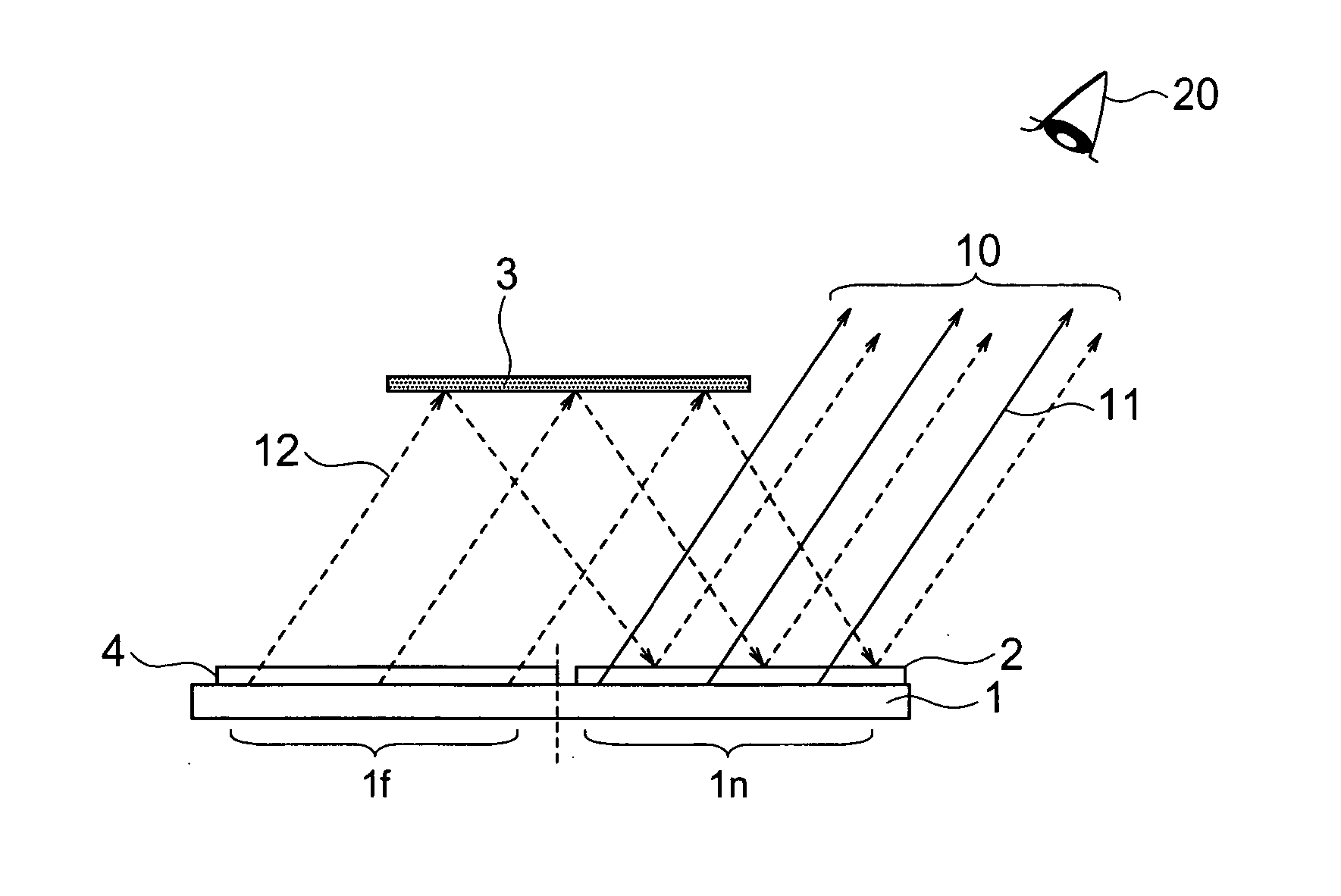
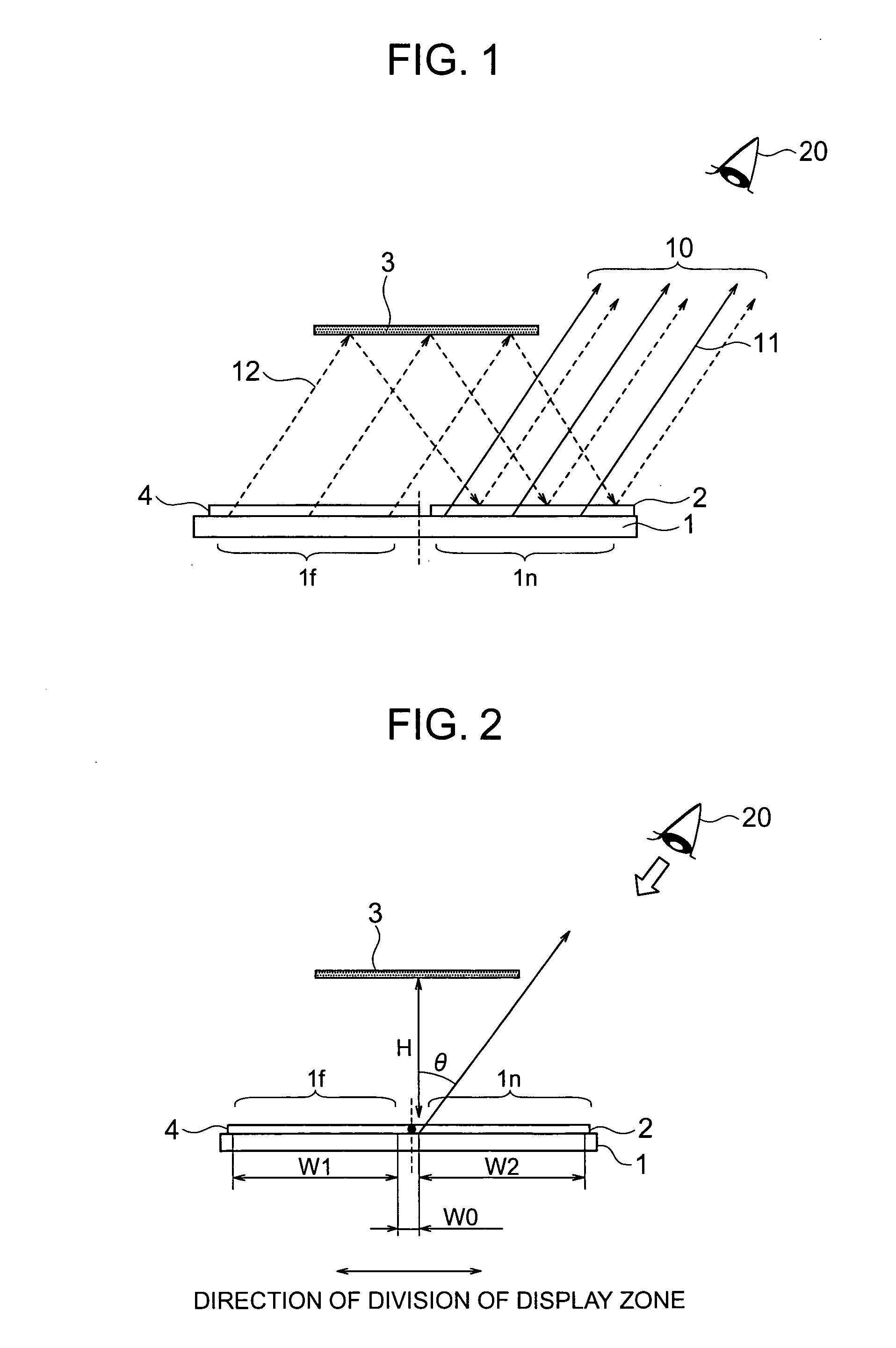
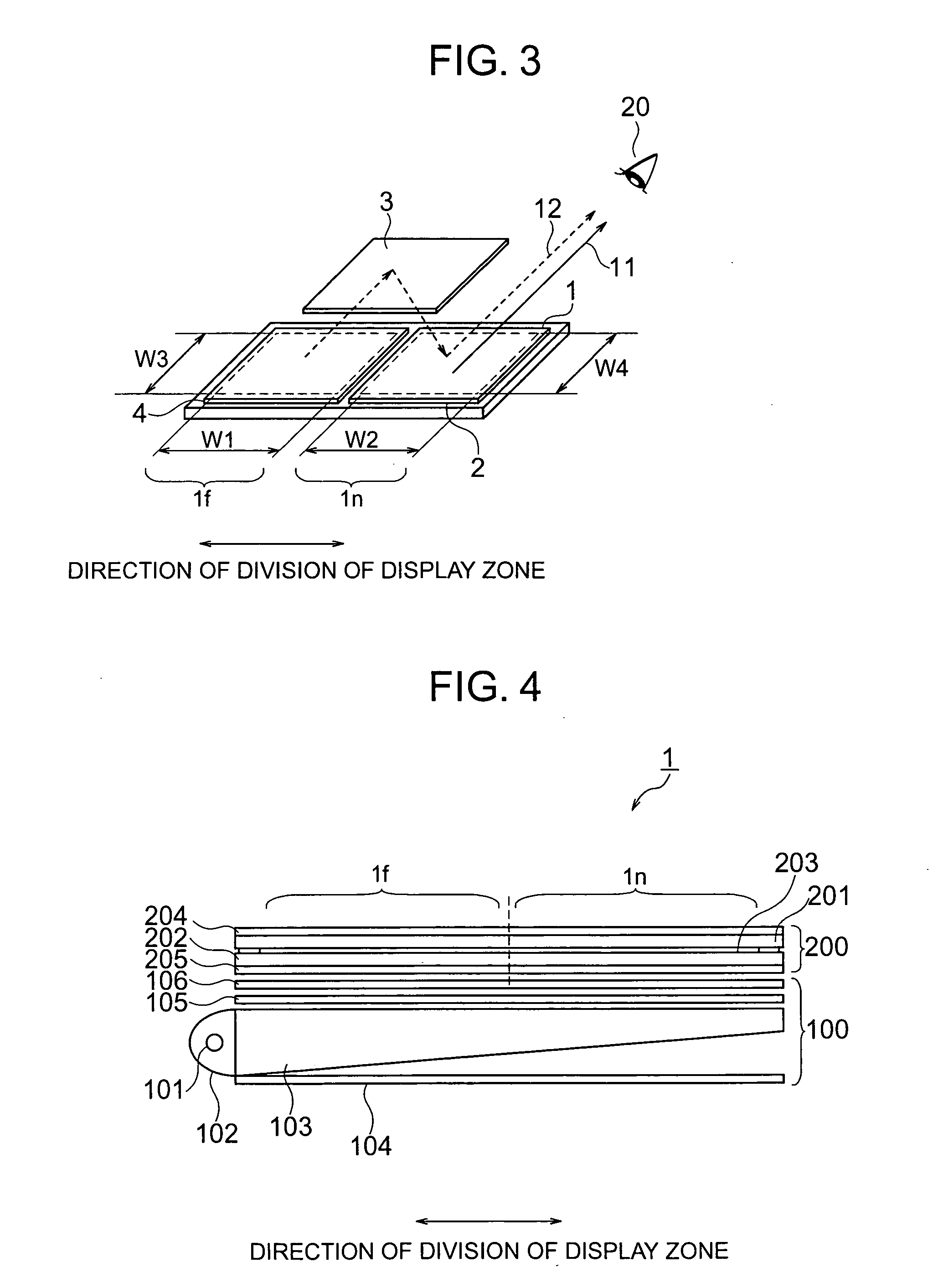
A thin display unit which display a plurality of objects to be viewed located at different depthwise positions viewed from the viewer so as to exhibit an image with depthwise feeling, comprising: a single display portion having a screen which is divided into a far-distant display zone and a near-distant display zone, a polarized beam splitting element located in front of the near-distant display zone, a polarized beam changing element located in front of the far-distant display zone, and a total reflection mirror for reflecting an image beam emitted from the far-distant display zone, onto the polarized beam splitting element, wherein an image beam emitted from the near-distant display zone is transmitted through the polarized beam splitting element and then viewed by the viewer, and an image beam emitted from the far-distant display zone is transmitted through the polarized beam changing element, then is reflected at the total reflection mirror, and thereafter is reflected by the polarized beam splitting element before it is viewed by the viewer.

Description

BACKGROUND OF THE INVENTION [0001] The present invention relates to a display unit which can superpose a plurality of objects to be viewed which are located at positions having different distances (depths) as viewed from the viewer, with one another and which can display the thus superposed image, to a method of displaying an image which gives a depth feel (three-dimensional effect) and to equipments incorporating thereof. [0002] There have been used direct-view display units for displaying images data, incorporating a display element such as a CRT (cathode ray tube), a plasma display panel, a liquid crystal display element or an organic electroluminescence display element, and a projection display unit for enlarging an optical image formed on a small-sized display element and then displaying the enlarged image on a screen. [0003] Any of these display units displays a two-dimensional image on the basis of two-dimensional image data. It is noted that a display element for displaying ...

Claims


Application Information

Patent Timeline
IPC IPC(8): G02B27/22H04N13/395G09G5/00
CPCG02B27/2278H04N13/0495H04N13/0425H04N13/395H04N13/327G02B30/52
Inventor ADACHI, MASAYAITOU, OSAMUKOMURA, SHINICHI
Owner PANASONIC LIQUID CRYSTAL DISPLAY CO LTD
Why Eureka
Try Eureka