Method of refilling a high speed print engine

a high-speed printhead and printhead technology, applied in the direction of printing, power drive mechanisms, inking apparatus, etc., can solve the problems of inability to replace these parts, and the printer unit employing reciprocating type printheads are considerably slow

Inactive Publication Date: 2005-07-21
MEMJET TECH LTD +1
View PDF27 Cites 37 Cited by
  • Summary
  • Abstract
  • Description
  • Claims
  • Application Information

AI Technical Summary

Benefits of technology

[0135] wherein the information stored by the storage element enables the reader to contro

Problems solved by technology

With such a printer unit it may be possible to remove the printhead for replacement, however the other parts of the print engine, such as the media transport rollers, control circuitry and maintenance stations, are typically fixed within the printer unit and replacement of these p

Method used


Image

  • Method of refilling a high speed print engine
  • Method of refilling a high speed print engine
  • Method of refilling a high speed print engine

Examples


Embodiment Construction

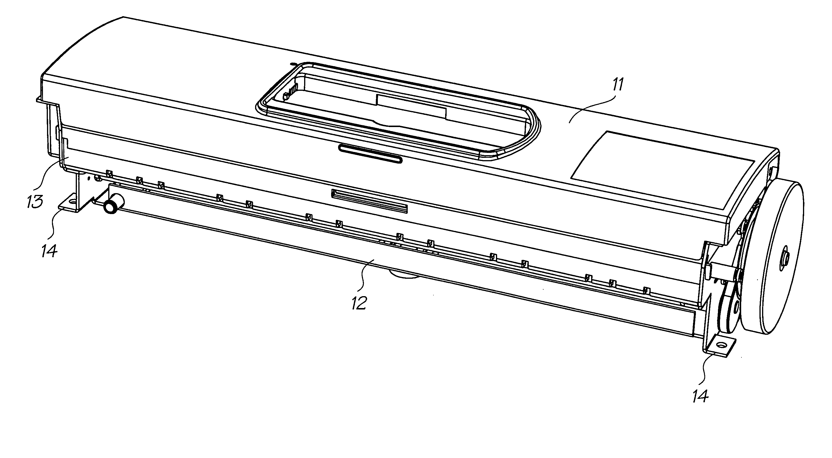
[0375] As discussed previously, the present invention resides in a print engine 1 that can be readily incorporated into a body of a printer unit 2 to perform the printing functions of the printer unit.

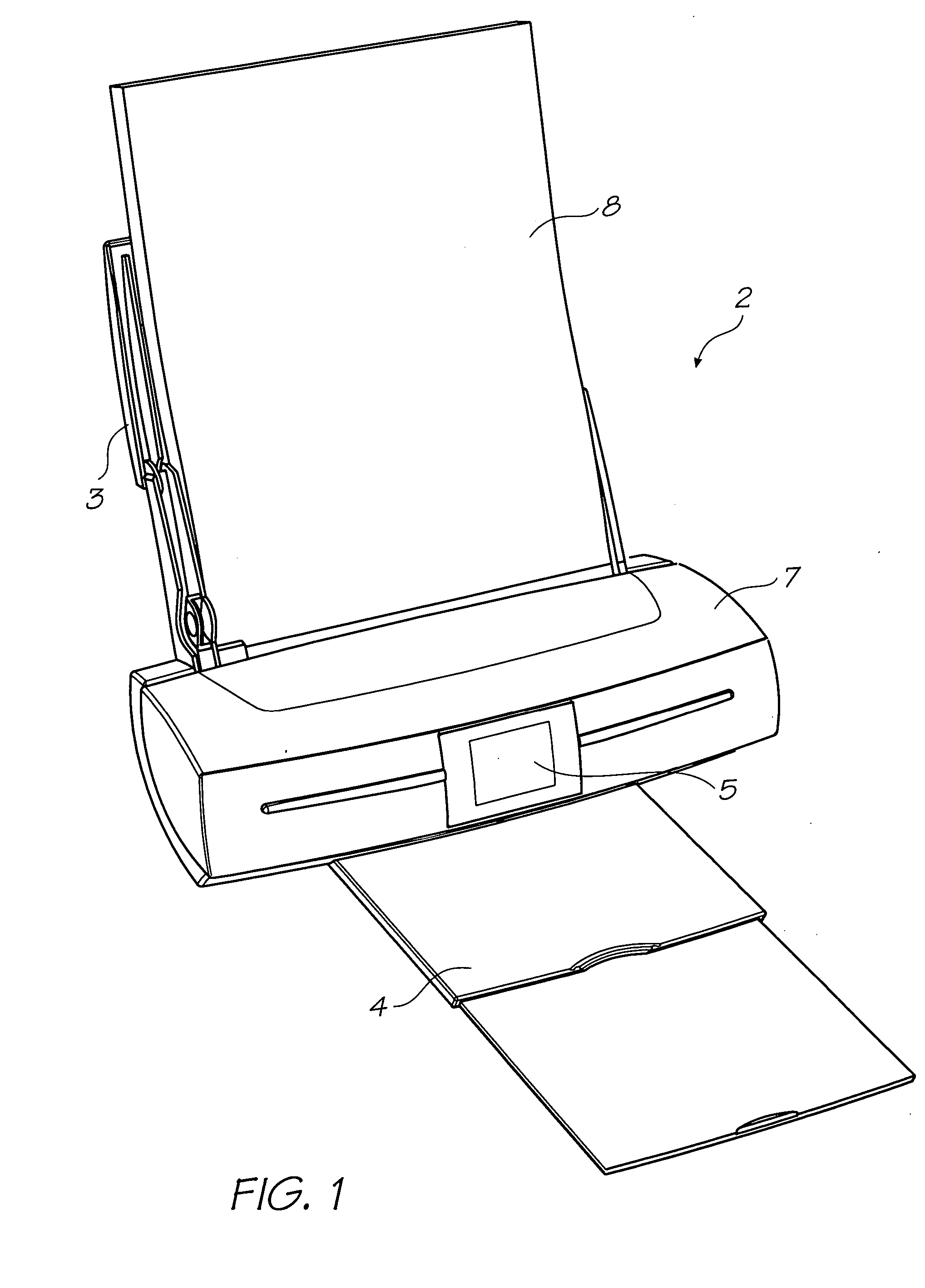
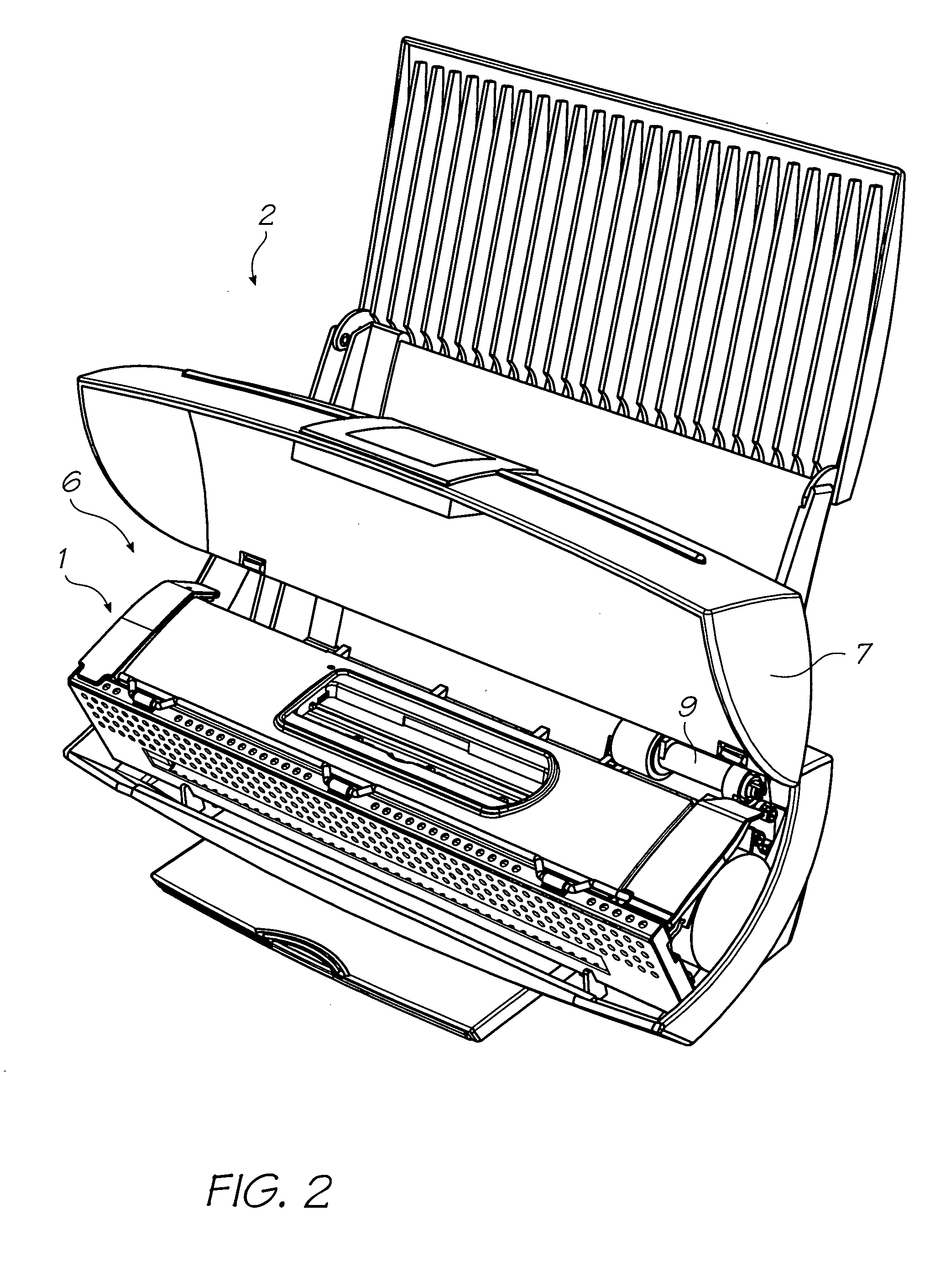
[0376] As shown in FIGS. 1 and 2, the printer unit 2, which incorporates the print engine 1, may be in any form but typically has a media supply region 3 for supporting and supplying media 8 to be printed by the print engine, and a media output or collection region 4 for collecting the printed sheets of media. The printer unit 2 may also have a user interface 5 for enabling a user to control the operation of the printer unit, and this user interface 5 may be in the form of an LCD touch screen as shown.

[0377] The printer unit 2 typically has an internal cavity 6 for receiving the print engine 1, and access to the internal cavity may be provided by a lid 7 which is hingedly attached to the body of the printer unit 2.

[0378] The print engine 1 is configured to be positioned and secured ...


PUM


Abstract

A method of refilling a supply of printing fluid in a printing unit, comprising the steps of: removably mounting a dispenser of printing fluid to the printing unit so as to align an outlet of the dispenser with an inlet of a printing fluid storage chamber of the printing unit; determining an amount of printing fluid needed to substantially refill the printing fluid storage chamber; and selectively dispensing an amount of printing fluid from the dispenser corresponding to the determined amount.

Description

[0001] The present application is a Continuation-In-Part application of U.S. Ser. No. 10 / 760,254 filed on Jan. 21, 2004. In the interests of brevity, the disclosure of the parent application is incorporated in its entirety into the present specification by cross reference.FIELD OF THE INVENTION [0002] The present invention relates to a high speed print engine for an inkjet printer unit, and more particularly to a method of refilling the print engine with a selected quantity of refill ink. CO-PENDING APPLICATIONS [0003] The following applications have been filed by the Applicant simultaneously with the present application: RRB001USRRB002USRRB003USRRB004USRRB005USRRB006USRRB007USRRB008USRRB009USRRB010USRRB011USRRB012USRRB013USRRB014USRRB015USRRB016USRRB017USRRB018USRRB019USRRB020USRRB021USRRB022USRRB023USRRB024USRRB025USRRB027USRRB030USRRB031USRRB032USRRB033USRRC001USRRC002USRRC003USRRC004USRRC005USRRC006USRRC007USRRC008USRRC009USRRC010USRRC011USRRC012USRRC013USRRC014USRRC015USRRC016...

Claims


Application Information

Patent Timeline
IPC IPC(8): B41J2/175B41J29/02
CPCB41J2/04541B41J2/17503B41J2/0458B41J2/04585B41J2/04591B41J2/14016B41J2/14427B41J2/155B41J2/1623B41J2/1628B41J2/1634B41J2/1637B41J2/1642B41J2/1648B41J2/16526B41J2/16535B41J2/16585B41J2/1707B41J2/1714B41J2/175B41J2/17506B41J2/17509B41J2/17513B41J2/1752B41J2/17536B41J2/17553B41J2/17556B41J2/17566B41J2/19B41J2/515B41J29/02B41J29/13B41J29/38B41J2002/14362B41J2002/14403B41J2002/14419B41J2002/14435B41J2002/14459B41J2002/14475B41J2002/14491B41J2002/1742B41J2002/17516B41J2202/19B41J2202/20B41J2202/21B41J2/135B41J2/04543B29C64/209B41J25/34
Inventor SILVERBROOK, KIANAKAZAWA, AKIRAHIBBARD, CHRISTOPHERMACKEY, PAUL IANBERRY, NORMAN MICHEALJACKSON, GARRY RAYMOND
Owner MEMJET TECH LTD
Why Eureka
Try Eureka