Circulating water anti-freezing system for solar heat collector

A technology of solar collector and antifreeze system, applied in solar thermal power generation, solar thermal device, heating device, etc., can solve the problems of high operating energy consumption and cost, low heat exchange efficiency, etc. High efficiency and smooth water return

Inactive Publication Date: 2010-09-29
HARBIN DEGUANG NEW ENERGY
View PDF6 Cites 2 Cited by
  • Summary
  • Abstract
  • Description
  • Claims
  • Application Information

AI Technical Summary

Problems solved by technology

[0003] The purpose of the present invention is to solve the problem that if the existing solar energy circulating water system wants to operate in winter, it is necessary to add heating tape to the outdoor pipeline or add antifreeze to the system, so that the energy consumption and cost of the system operation are high, and the heat exchange efficiency is low problem, provide a solar collector circulating water antifreeze system

Method used


Image

  • Circulating water anti-freezing system for solar heat collector
  • Circulating water anti-freezing system for solar heat collector

Examples


specific Embodiment approach 1

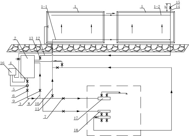
[0007] Specific implementation mode 1: Combination figure 1 To illustrate this embodiment, this embodiment includes the heat preservation water tank 2, the first pipeline 3, the first valve 4, the circulating pump 5, the second valve 6, the third valve 7, the second pipeline 8, the fourth valve 9, and the The third pipeline 10, the fifth valve 11, the fourth pipeline 12, the sixth valve 13, the exhaust air pipe 14, the exhaust air valve 15, the automatic temperature difference controller 16 of the circulating pump, and at least one plate solar collector 1. The input end of a pipeline 3 is connected to the water outlet of the heat preservation water tank 2, the output end of the first pipeline 3 is connected to the domestic water device 16 or the heating device 17, the first valve 4, the circulating pump 5, the second valve 6 and the The three valves 7 are sequentially arranged on the first pipeline 3 from the input end to the output end of the first pipeline 3, the input end of...

specific Embodiment approach 2

[0008] Specific implementation manner two: combination figure 1 Describing this embodiment, the angle between the plate-type solar heat collector 1 of this embodiment and the horizontal plane is 10 degrees to 90 degrees. This design can ensure that the water in the plate-type solar collector 1 can return to the water tank by gravity. The other components and connection relationships are the same as in the first embodiment.

[0009] The working principle of the present invention: the exhaust and intake valve 15 is normally open. When the circulating pump 5 is working, the first valve 4 and the second valve 6 are both open. When the exhaust and intake valve 15 overflows, adjust the sixth valve 13 , So that the water in the plate-type solar heat collector 1 quickly flows into the heat preservation water tank 2.


PUM


Abstract

The invention provides a circulating water anti-freezing system for a solar heat collector, which relates to a solar circulating water system. The invention solves the problem that when the current solar circulating water system is operated in winter, heat tapes need to be additionally arranged on outdoor pipelines or anti-freezing fluid needs to be filled into the system, thus the operation energy consumption and cost of the system are higher, and the heat exchange efficiency is low. An input end of a first pipeline is connected with an insulating water tank; a first valve, a circulating pump, a second valve and a third valve are successively arranged on the first pipeline from the input end to the output end of the first pipeline; one end of a fourth pipeline is connected with a return water pipe on the plate solar heat collector and the other end is communicated with the insulating water tank; an air inlet and outlet pipe is arranged on the return water pipe of the plate solar heat collector, and the other end is communicated with atmosphere; the inner diameter of the fourth pipeline is the same as the inner diameters of the return water pipe and a water supply pipe in the plate solar heat collector; and the inner diameters of the first pipeline, the second pipeline and the third pipeline are smaller than the inner diameter of the fourth pipeline. The invention is suitable for use in winter in the north.

Description

Technical field [0001] The invention relates to a solar circulating water system. Background technique [0002] In the cold northern winter, in order to ensure that the circulating water of the solar collector is not frozen in winter, that is, it can operate normally when there is sunlight, usually a heating cable is added to the outdoor solar circulating water system to prevent the water in the system from freezing. This method The disadvantage of this method is to increase the energy consumption and cost of system operation; another method is to use antifreeze as the heat exchange medium in the solar circulating water system. The disadvantage of this method is low heat exchange efficiency and high operating cost. Summary of the invention [0003] The purpose of the present invention is to solve the problem that if the existing solar circulating water system wants to operate in winter, it is necessary to add heat tracing to the outdoor pipeline or add antifreeze to the system, so...

Claims


Application Information

Patent Timeline
Patent Type & Authority Applications(China)
IPC IPC(8): F24J2/46
CPCY02E10/40
Inventor 高德广
Owner HARBIN DEGUANG NEW ENERGY
Why Eureka
Try Eureka