Coating nozzle cleaning device

A technology for cleaning devices and nozzles, which is applied to cleaning methods and tools, cleaning methods using tools, cleaning methods using liquids, etc., and can solve problems such as the inability to effectively clean the mixture of photoresist and cleaning fluid

Inactive Publication Date: 2018-11-23
WUHAN CHINA STAR OPTOELECTRONICS TECH CO LTD
View PDF6 Cites 2 Cited by
  • Summary
  • Abstract
  • Description
  • Claims
  • Application Information

AI Technical Summary

Problems solved by technology

[0005] The purpose of the present invention is to provide a coating nozzle cleaning device to solve the problem that the prior art cannot effectively clean the mixture of photoresist and cleaning solution

Method used


Image

  • Coating nozzle cleaning device
  • Coating nozzle cleaning device
  • Coating nozzle cleaning device

Examples


Embodiment Construction

[0027] The following will clearly and completely describe the technical solutions in the embodiments of the present invention with reference to the drawings in the embodiments of the present invention.

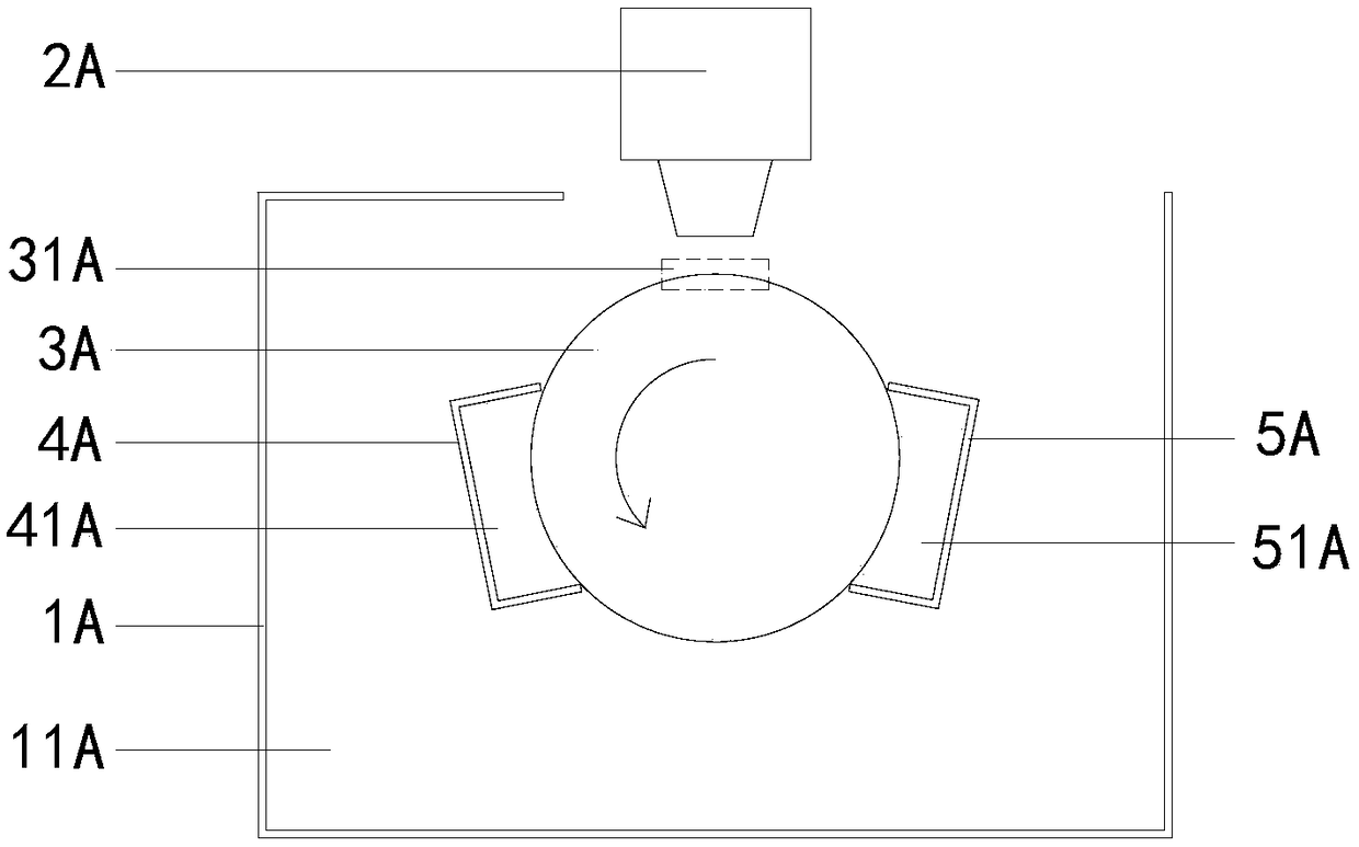
[0028] from figure 1 It can be seen that the first embodiment of the coating nozzle cleaning device of the present invention includes:

[0029] Chassis 1A, such as figure 1 As shown, the interior of the casing 1A is provided with a component accommodating cavity 11A, which is used to place various components of the coating nozzle cleaning device, and the upper part of the casing 1A is an open structure, so that the component accommodating cavity 11A and the The external conduction facilitates the coating nozzle 2A to move into the device accommodation chamber 11A for cleaning.

[0030] Roller 3A, such as figure 1 As shown, the roller 3A is arranged in the device accommodation cavity 11A, the roller 3A is a cylindrical structure, the roller 3A can rotate with its central axi...


PUM


Abstract

The invention discloses a coating nozzle cleaning device which comprises a roller, a main cleaning device and an auxiliary cleaning device. The area occupied by one part of the roller is a coating area; the roller can self-rotate; the main cleaning device is arranged outside the coating area and is provided with a main liquid holding cavity; one part of the roller is placed in the main liquid holding cavity; the auxiliary cleaning device is arranged outside the coating area and is internally provided with an auxiliary liquid holding cavity; one part of the roller is arranged in the auxiliary liquid holding cavity; the part, passing through the coating area, of the roller during self-rotating can pass through the main liquid holding cavity and the auxiliary liquid holding cavity along withthe self-rotation of the roller; and at the time, only a photoresistor cleaning fluid needs to be injected into the main liquid holding cavity so as to clean the a photoresistor, and only pure water needs to be injected into the auxiliary liquid holding cavity so as to clean a mixture of the photoresistor and the photoresistor cleaning fluid, so that the problem that the mixture of the photoresistor and the cleaning fluid cannot be effectively cleaned in the prior art can be solved.

Description

technical field [0001] The invention relates to a nozzle cleaning device, in particular to a coating nozzle cleaning device. Background technique [0002] In the production process of the TFT (Thin Film Transistor, which is the abbreviation of thin film transistor) side exposure part, it is necessary to clean the glass substrate, coat the photoresist, bake, enter the exposure machine, and define the pattern of the photoresist on the glass substrate. , Finally, the graphics are displayed through the developing process. [0003] Among them, after the glass substrate is cleaned, it will enter the coating unit for photoresist coating. Before coating, the coating nozzle will be cleaned. To ensure the uniform film thickness of the front end of the glass substrate during coating; when the roller starts to rotate, the pre-discharged photoresist will be brought into the photoresist cleaning liquid of the lower cleaning roller with the rotation of the roller, and then the roller will...

Claims


Application Information

Patent Timeline
Patent Type & Authority Applications(China)
IPC IPC(8): B08B3/08B08B1/02B08B3/02
CPCB08B1/02B08B3/022B08B3/08
Inventor 吕良
Owner WUHAN CHINA STAR OPTOELECTRONICS TECH CO LTD
Why Eureka
Try Eureka