
Electronic stethoscope with piezo-electrical film contact microphone

a technology of piezoelectric film and stethoscope, which is applied in the field of stethoscope, can solve the problems of increasing the workload of doctors, affecting the accuracy of stethoscope,

Inactive Publication Date: 2005-07-21
HEALTH & LIFE CO LTD
View PDF4 Cites 45 Cited by
  • Summary
  • Abstract
  • Description
  • Claims
  • Application Information

AI Technical Summary

Benefits of technology

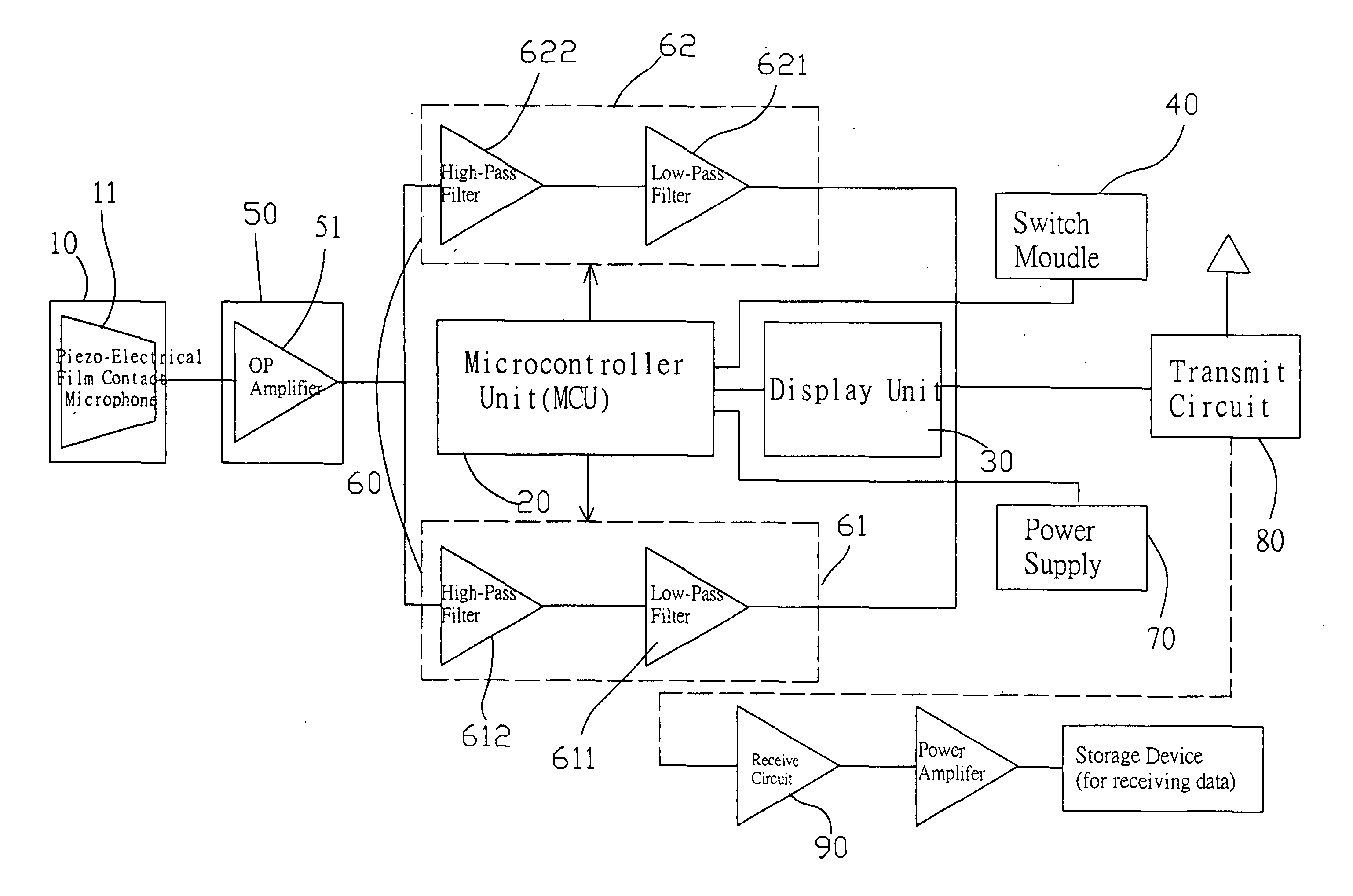
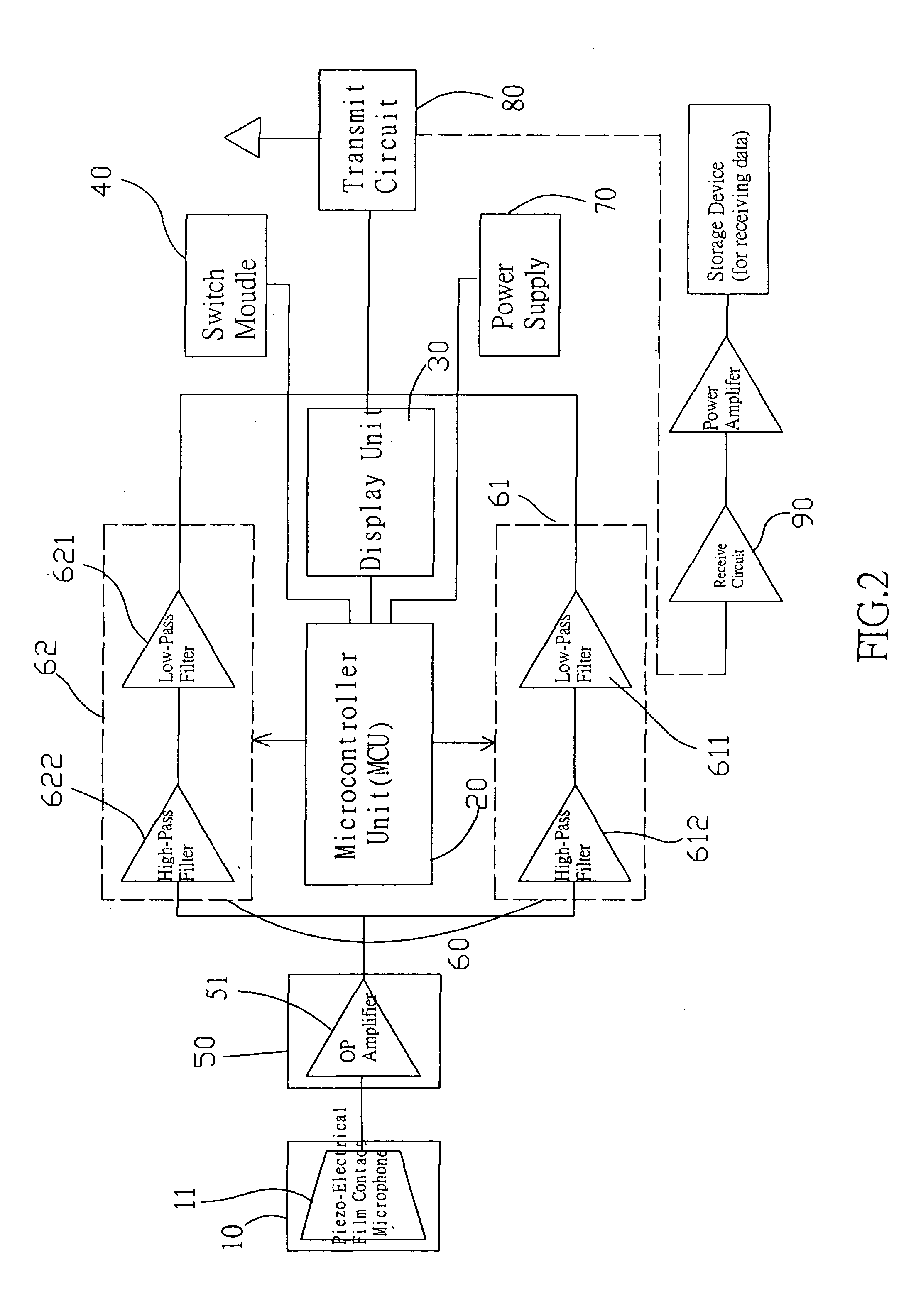
[0005] The microcontroller unit is connected to a front-end operational amplifier (OP-amp) circuit, a wave filter circuit, and a transmit circuit, such that when the stethoscope is used, the weak sound signal received by contacting stethoscope head to a patient's body is sent to the OP amplifier. The amplified sound signal (such as heart sound and lung sound) selectively measured by the switch module is processed by the microcontroller unit and the wave filter. The filtered sound signal is sent to a transmit / receive circuit, so that the wave filter circuit can filter the noise of the sound signal produced by human bodies under the control of the microcontroller unit, and medical people can make correct diagnostics based on the correct sound received through the transmit / receive circuits.

Problems solved by technology

Furthermore, the long-distance travel of the sound also causes a significant loss to the intensity of the sound.
Therefore, traditional stethoscope not only has limitations on its acoustic performance, but also requires doctors to pay more attention to its use and concentrate on listening to the tiny sound signals from different parts of the patient's body.
Therefore, it usually requires doctors to have some experience on using this device for a correct diagnostic, since doctors may easily misjudge a case due to human factors.
Such stethoscope is not good for its application at all.

Method used


Image

  • Electronic stethoscope with piezo-electrical film contact microphone
  • Electronic stethoscope with piezo-electrical film contact microphone
  • Electronic stethoscope with piezo-electrical film contact microphone

Examples


Embodiment Construction

[0014] To make it easier for our examiner to understand the objective of the invention, its structure, innovative features, and performance, we use a preferred embodiment together with the attached drawings for the detailed description of the invention.

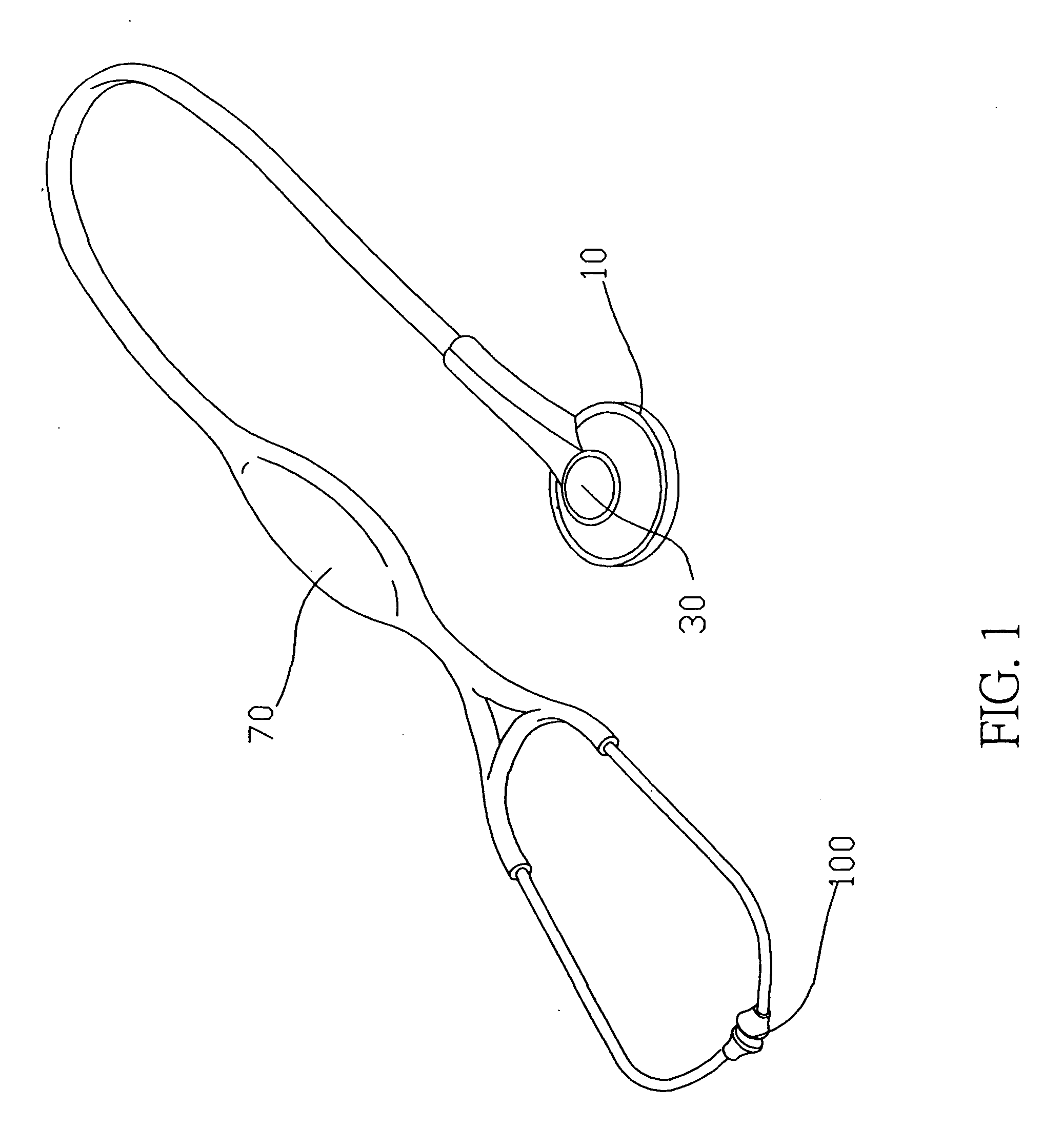
[0015] Please refer to FIGS. 1, 2 and 3 for the electronic stethoscope with a Piezo-Electrical Film contact microphone according to the present invention comprising a stethoscope head 10 with a Piezo-Electrical Film contact microphone 11 inside, and the stethoscope head 10 is electrically connected to a circuit and a microcontroller unit (MCU) 20. The MCU chips used in this embodiment is TMP86CM23U. The microcontroller unit 20 is connected to a display unit 30 and a switch module 40 by an electric circuit, wherein the display unit is an LCD monitor, and the switch module 40 has one or more switches for switching between the heart sound mode and the lung sound mode.

[0016] Further, the stethoscope head 10 is connected to a front-end o...


PUM


Abstract

The present invention discloses an electronic stethoscope with a Piezo-Electrical Film contact microphone comprising a stethoscope head with a Piezo-Electrical Film contact microphone inside, and the stethoscope head is electrically connected to a circuit and a microcontroller unit (MCU). The microcontroller unit is connected to a front-end operational amplifier (OP-amp) circuit, a wave filter circuit, and a transmit circuit, such that when the stethoscope is used, the weak sound signal received by contacting stethoscope head with a human body is sent to the OP amplifier. The amplified sound signal (such as heart sound and lung sound) selectively measured by the switch module is processed by the microcontroller unit and the wave filter. The filtered sound signal is sent to a transmit / receive circuit, so that the wave filter circuit can filter the noise of the sound signal produced by human bodies under the control of the microcontroller unit, and medical people can make correct diagnostics based on the correct sound received through the transmit / receive circuits.

Description

FIELD OF THE INVENTION [0001] The present invention relates to an electronic stethoscope with a contact microphone, which uses an electric circuit to amplify a weak sound signal (such as heart sound or lung sound) produced by human bodies, so that the sound signal can be separated from other noises, and allows medical people to make correct diagnostics. BACKGROUND OF THE INVENTION [0002] Stethoscope is the one of the oldest and most original diagnostic tools. As stethoscope had been invented for more than two centuries, substantial improvements to overcome the shortcomings of the traditional stethoscope were made by electronic methods. Since the structure of the stethoscope generally uses a long empty tube to pass biological sounds to a doctor's ear, and the resonance so produced distorts the sound. Furthermore, the long-distance travel of the sound also causes a significant loss to the intensity of the sound. Therefore, traditional stethoscope not only has limitations on its acoust...

Claims


Application Information

Patent Timeline
IPC IPC(8): A61B5/00A61B7/04
CPCA61B7/04A61B5/0002
Inventor YANG, PAUL
Owner HEALTH & LIFE CO LTD
Learn More