Simplified dual mode medical oxygen concentrator

a dual-mode, oxygen concentrator technology, applied in the direction of process and machine control, separation processes, instruments, etc., can solve the problem of difficult economic design of small oxygen generation systems with high turndown ratios

Active Publication Date: 2005-07-28
AIR PROD & CHEM INC
View PDF12 Cites 32 Cited by
  • Summary
  • Abstract
  • Description
  • Claims
  • Application Information

AI Technical Summary

Benefits of technology

[0019]FIG. 4 is a schematic diagram of a ...

Problems solved by technology

The economic design of small oxygen generation systems with high turndown ratios is difficult...

Method used


Image

  • Simplified dual mode medical oxygen concentrator
  • Simplified dual mode medical oxygen concentrator
  • Simplified dual mode medical oxygen concentrator

Examples


exemplary embodiment 1

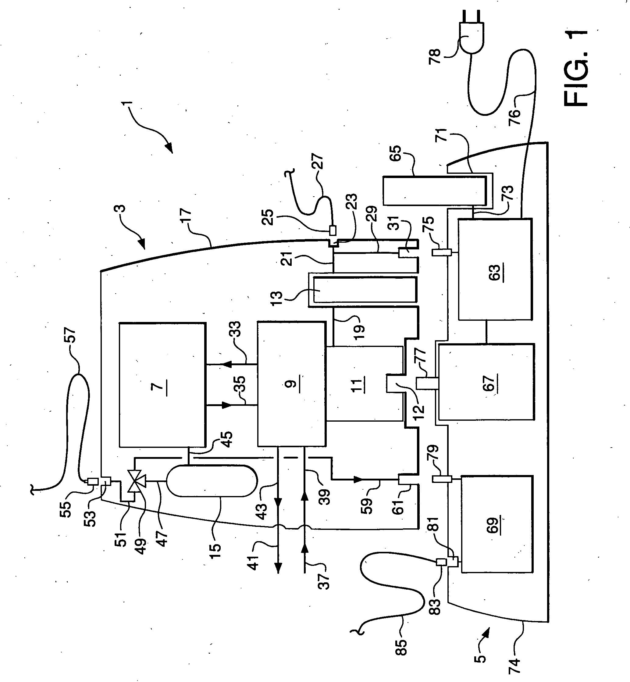
[0069] This embodiment uses the system of FIG. 1 as described above. In this embodiment, portable air separation device 7 is a PSA system sized to deliver 0.5 to 5 LPM of oxygen-rich gas product with a purity of at least 80 mole % oxygen. Gas pump 9 is designed to provide sufficient pressurized air feed to the PSA system and withdraw sufficient waste gas from the PSA system so that the system can generate the required range of 0.5 to 5 LPM of oxygen-rich gas product. Gas pump primary drive motor 11 is designed to drive gas pump 9 to provide sufficient air to the portable air separation device to generate 0.5 to 3 LPM of oxygen-rich gas. Booster motor 67 in stationary base unit 5 is designed to drive the primary gas pump to provide sufficient air to the portable air separation device to generate 0 to 2 LPM of oxygen-rich gas. Primary drive motor 11 is designed to be coupled with booster motor 67, and the coupled drive motors are designed to provide sufficient air to the portable air ...

exemplary embodiment 1a

[0073] This embodiment is identical to Embodiment 1 except for the method of driving gas pump 9 in the coupled mode. In the present embodiment, all power to drive gas pump 9 in the coupled mode is supplied by motor 67 via shaft coupling 77 and shaft connector 12. Motor 67 is a larger motor than that used as the booster motor in Embodiment 1 described above. Primary drive motor 11 is idle in this alternative version, and therefore the service life of this motor is increased because the motor is operated only in the portable mode. Motor 67 thus is sized to drive gas pump 9 so that the PSA system in portable air separation device 7 can generate 0.5 to 5 LPM of oxygen-rich product gas.

exemplary embodiment 2

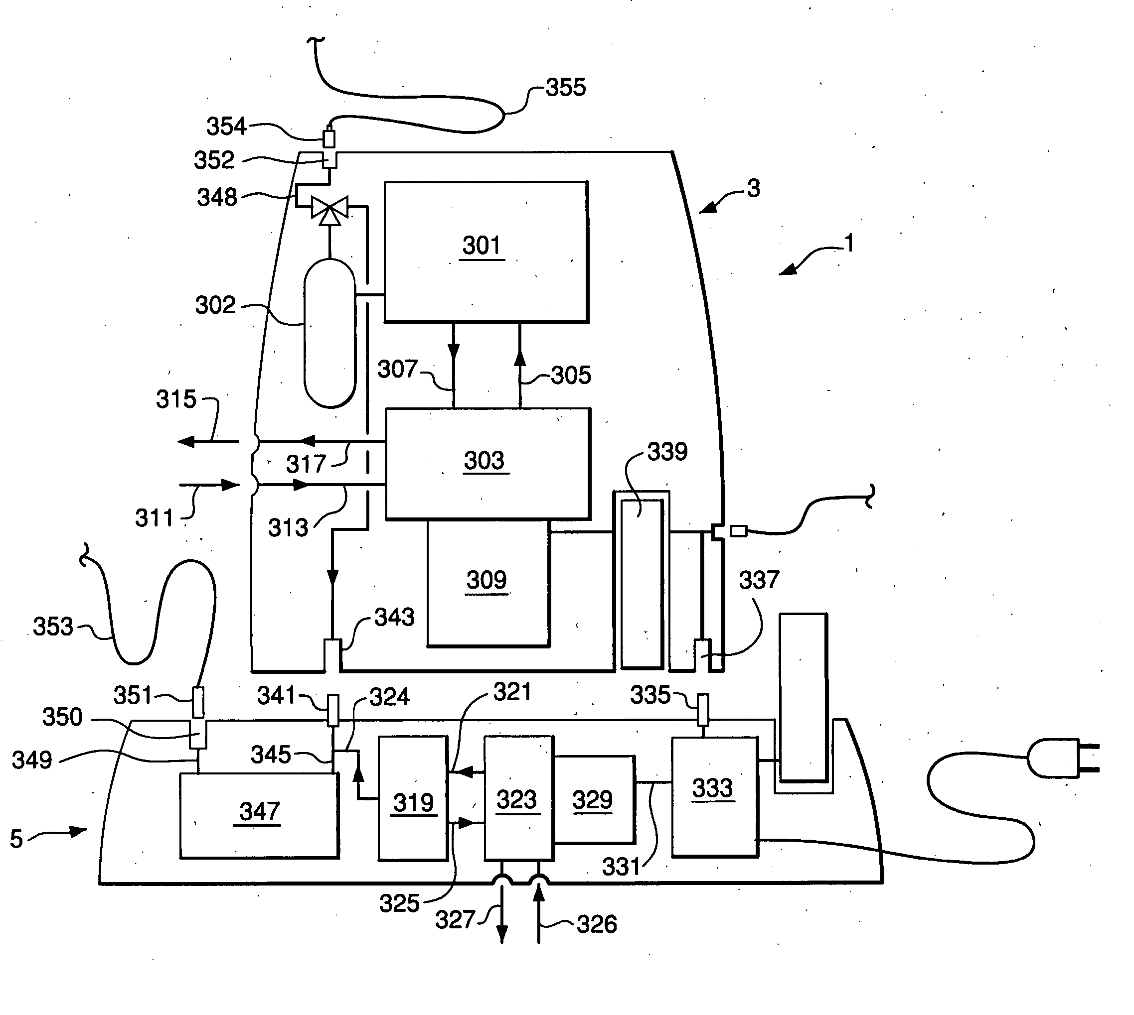
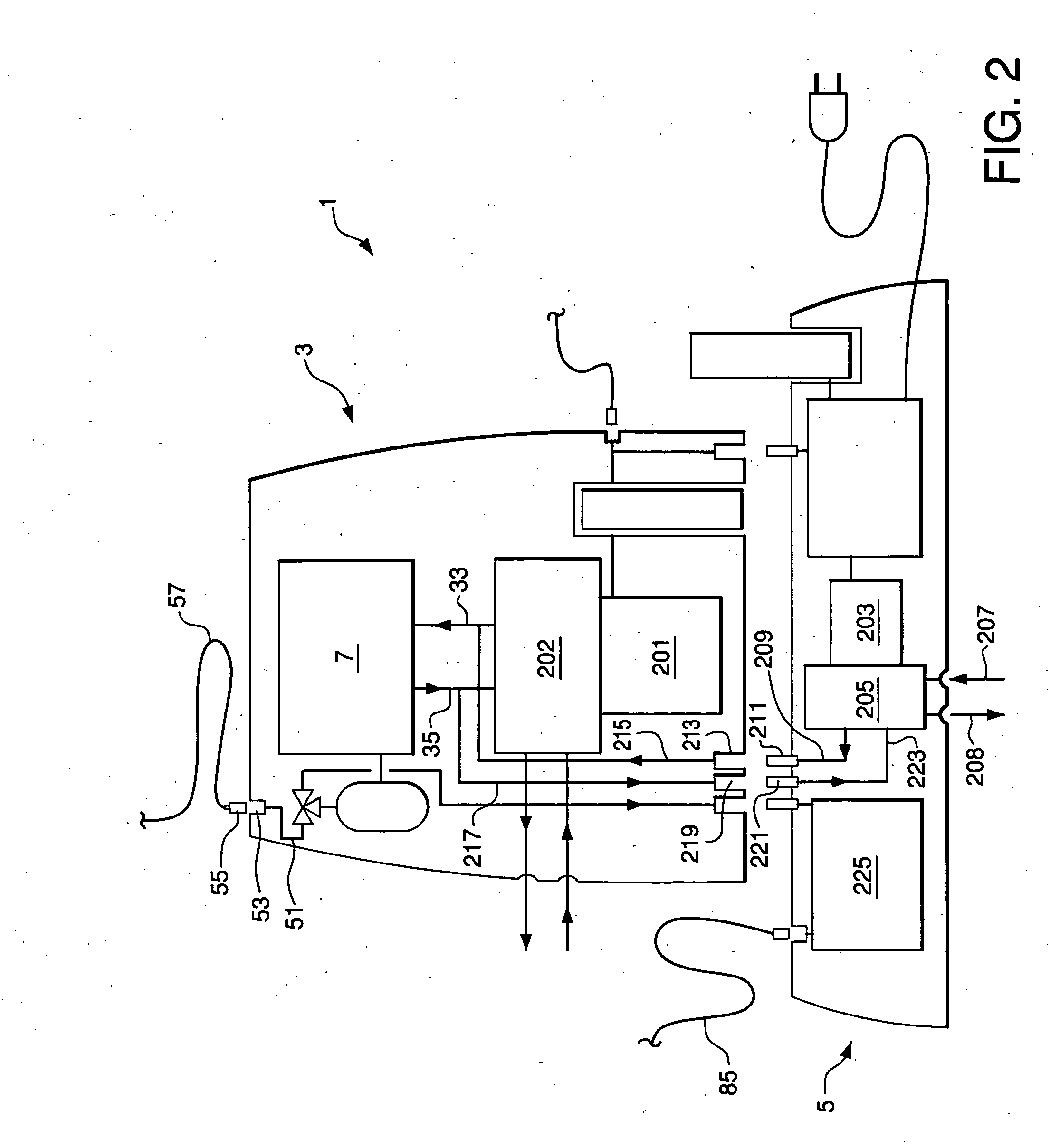
[0074] This embodiment uses the system of FIG. 2 as described above. In this embodiment, portable air separation device 7 is a PSA system sized to deliver 0.5 to 5 LPM of oxygen-rich gas product with a purity of at least 80 mole % oxygen. Gas pump 202 is designed to provide sufficient pressurized air feed to the PSA system and withdraw sufficient waste gas from the PSA system so that the system can generate 0.5 to 3 LPM of oxygen-rich gas product. Gas pump 202 therefore is smaller than gas pump 9 of Embodiment 1. Gas pump primary drive motor 201 is designed in the present embodiment to drive gas pump 202 to provide sufficient air to the portable air separation device to generate 0.5 to 3 LPM of oxygen-rich gas.

[0075] Drive motor 203 and supplemental gas pump 205 are disposed in stationary base unit 5 and are sized to provide sufficient air to the portable air separation device to generate 0 to 2 LPM of oxygen-rich gas.

[0076] In this exemplary embodiment, portable oxygen generator ...


PUM

PropertyMeasurementUnit
Fractionaaaaaaaaaa
Pressureaaaaaaaaaa
Poweraaaaaaaaaa

Abstract

Oxygen concentrator system comprising a portable oxygen generator unit adapted to generate a non-humidified oxygen-rich gas and a stationary base unit adapted to generate a humidified oxygen-rich gas, wherein the portable oxygen generator unit and the stationary base are adapted for operation in a coupled mode and an uncoupled mode. The portable oxygen generator unit includes a first flow coupling adapted to receive the humidified oxygen-rich gas when operating in the coupled mode, piping means adapted to combine the non-humidified oxygen-rich gas and the humidified oxygen-rich gas to form a humidified oxygen-rich gas product, and an oxygen-rich gas product delivery port. The stationary base unit is adapted to recharge a rechargeable power supply system in the portable oxygen generator unit when the units are coupled.

Description

CROSS-REFERENCE TO RELATED APPLICATIONS [0001] This application is a Continuation-In-Part of Ser. No. 10 / 762,785, which was filed on Jan. 22, 2004 and which is incorporated herein by reference.BACKGROUND OF THE INVENTION [0002] The supply of therapeutic oxygen to patients in homes and other residential settings is an important and growing segment of the health care industry. Oxygen can be supplied to a patient by liquid or compressed oxygen with an appropriate vaporization or pressure regulation system and a gas delivery cannula. Alternatively, oxygen can be supplied by the generation of oxygen using a small onsite air separation device located near the patient that delivers the generated oxygen via a cannula. This latter mode of oxygen supply is preferred by many patients, and numerous small air separation devices have been developed in response to this demonstrated need. [0003] Respiratory oxygen usage rates typically range up to 3 LPM (liters per minute at 22° C. and 1 atma press...

Claims


Application Information

Patent Timeline
IPC IPC(8): A61M16/00A61M16/16A62B7/00A62B7/10B01D53/02B01D53/053
CPCB01D53/0473B01D2259/4541B01D53/053B01D2253/104B01D2253/108B01D2253/304B01D2256/12B01D2257/102B01D2257/80B01D2259/40005B01D2259/40041B01D2259/40052B01D2259/40069B01D2259/40071B01D2259/4061B01D2259/4146B01D2259/4533B01D53/0476
Inventor WHITLEY, ROGER DEANWAGNER, GLENN PAULLABUDA, MATTHEW JAMES
Owner AIR PROD & CHEM INC
Why Eureka
Try Eureka