Video surveillance system

a video surveillance and video technology, applied in the field of automatic video surveillance, can solve problems such as the analysis of video surveillance data, and achieve the effect of reducing the amount of video surveillance data

Inactive Publication Date: 2005-07-28
AVIGILON FORTRESS
View PDF106 Cites 223 Cited by
  • Summary
  • Abstract
  • Description
  • Claims
  • Application Information

AI Technical Summary

Benefits of technology

[0033] An object of the invention is to reduce the amount of video surve

Problems solved by technology

Unfortunately, conventional video surveillance systems produce such prodigious volumes

Method used


Image

  • Video surveillance system
  • Video surveillance system
  • Video surveillance system

Examples


Embodiment Construction

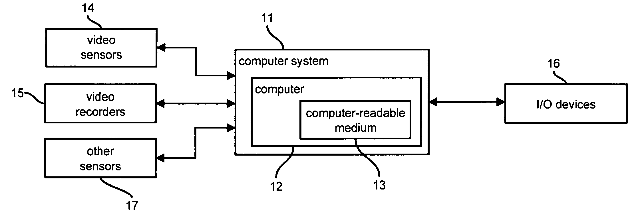
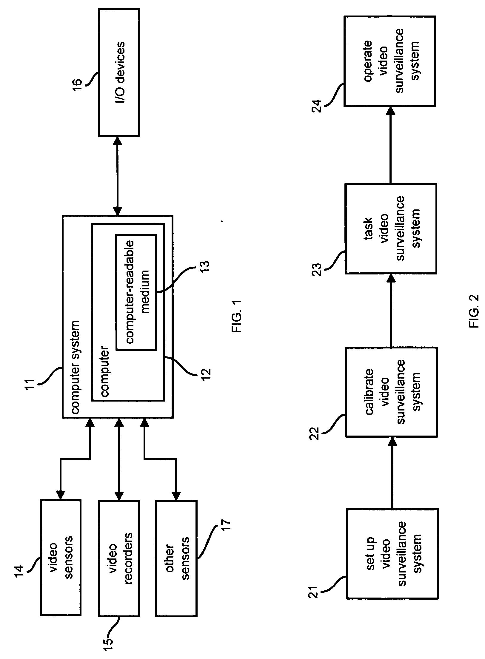
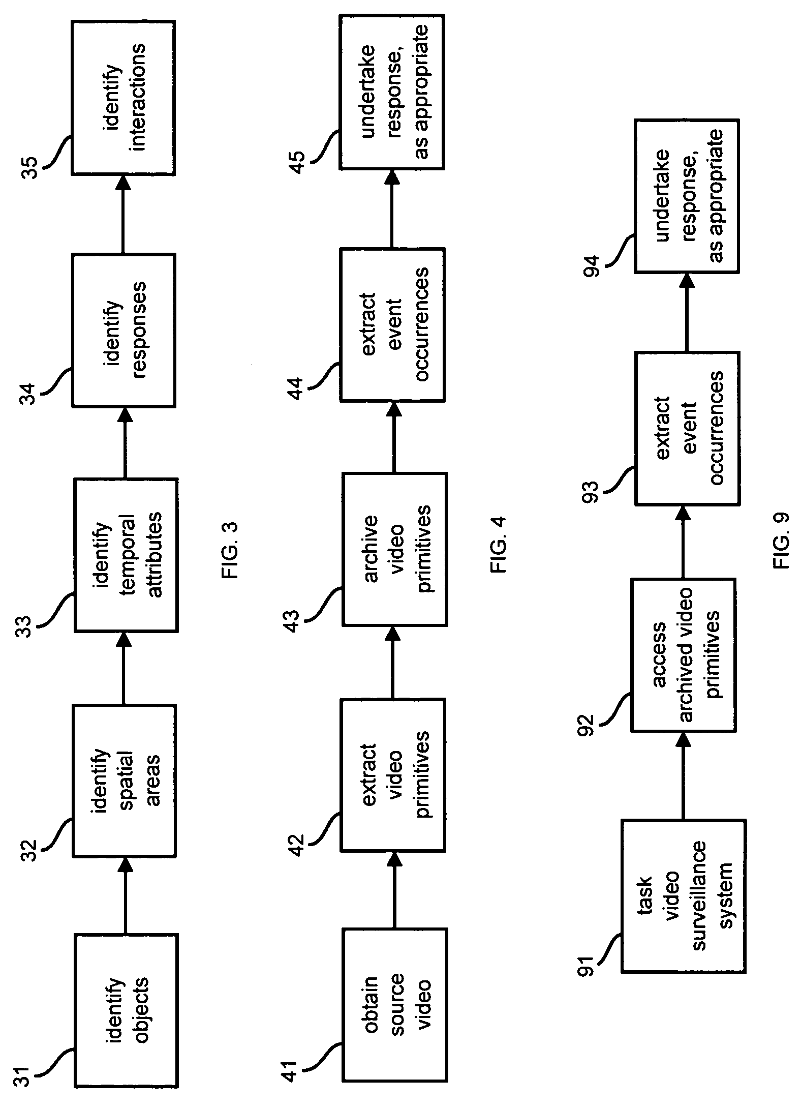
[0074] The automatic video surveillance system of the invention is for monitoring a location for, for example, market research or security purposes. The system can be a dedicated video surveillance installation with purpose-built surveillance components, or the system can be a retrofit to existing video surveillance equipment that piggybacks off the surveillance video feeds. The system is capable of analyzing video data from live sources or from recorded media. The system is capable of processing the video data in real-time, and storing the extracted video primitives to allow very high speed forensic event detection later. The system can have a prescribed response to the analysis, such as record data, activate an alarm mechanism, or activate another sensor system. The system is also capable of integrating with other surveillance system components. The system may be used to produce, for example, security or market research reports that can be tailored according to the needs of an ope...


PUM


Abstract

A video surveillance system is set up, calibrated, tasked, and operated. The system extracts video primitives and extracts event occurrences from the video primitives using event discriminators. The system can undertake a response, such as an alarm, based on extracted event occurrences.

Description

CROSS-REFERENCE TO RELATED APPLICATIONS [0001] This application is a continuation-in-part of U.S. patent application Ser. No. 09 / 987,707, filed on Nov. 15, 2001, which claims the priority of U.S. patent application Ser. No. 09 / 694,712, filed on Oct. 24, 2000, both of which are incorporated herein by reference.BACKGROUND OF THE INVENTION [0002] 1. Field of the Invention [0003] The invention relates to a system for automatic video surveillance employing video primitives. [0004] 2. References [0005] For the convenience of the reader, the references referred to herein are listed below. In the specification, the numerals within brackets refer to respective references. The listed references are incorporated herein by reference. [0006] The following references describe moving target detection: [0007] {1} A. Lipton, H. Fujiyoshi and R. S. Patil, “Moving Target Detection and Classification from Real-Time Video,”Proceedings of IEEE WACV '98, Princeton, N.J., 1998, pp. 8-14. [0008] {2} W. E. L...

Claims


Application Information

Patent Timeline
IPC IPC(8): G06F17/30G06K9/00G06T7/20G08B13/196H04N5/272H04N7/18H04N7/24
CPCG06F17/3079H04N21/44012G06F17/30805G06F17/30811G06F17/30823G06K9/00771G06T7/20G08B13/19606G08B13/19608G08B13/1961G08B13/19615G08B13/19663G08B13/19667G08B13/19673G08B13/19684G08B13/19695H04N5/272H04N7/18H04N21/23412H04N21/234318G06F17/30802G06F16/7854G06F16/786G06F16/73G06F16/7837G06F16/785G06V20/52G08B13/196
Inventor VENETIANER, PETER L.LIPTON, ALAN J.CHOSAK, ANDREW J.FRAZIER, MATTHEW F.HAERING, NIELSMYERS, GARY W.YIN, WEIHONGZHANG, ZHONG
Owner AVIGILON FORTRESS
Why Eureka
Try Eureka