Optical disk apparatus and method of recording with optical disk apparatus

a technology of optical disk and optical disk, applied in the direction of data recording, disposition/mounting of heads, instruments, etc., can solve problems such as degradation of recording quality, and achieve the effects of avoiding the positional relationship, stable recording operations, and avoiding degradation of recording quality

Inactive Publication Date: 2005-07-28
PANASONIC CORP
View PDF3 Cites 7 Cited by
  • Summary
  • Abstract
  • Description
  • Claims
  • Application Information

AI Technical Summary

Benefits of technology

[0021] According to the invention, the above-described configuration makes it possible to conduct full-surface tilt learning at the time of activation on a printable medium that can be warped by an internal temperature increase during a recording operation. It is thus possible to prevent the positional relationship between a surface of the optical disk and the optical axis of the laser from shifting from perpendicularity to cause degradation of recording quality and a recording error attributable to a failure in detecting address information on an optical disk, such a shift being caused by warping of the optical disk which starts when recording is started on the entire surface of the disk and proceeds as the temperature increases during recording to reach a state of warping different from the result of the full-surface tilt learning conducted at the time of activation. Degradation of recording quality can be also avoided by correcting a positional shift of a point in focus that occurs between the optical disk surface and an objective lens. It is therefore possible to provide an optical disk apparatus which can perform stable recording operations and achieve stable recording quality.

Problems solved by technology

It is thus possible to prevent the positional relationship between a surface of the optical disk and the optical axis of the laser from shifting from perpendicularity to cause degradation of recording quality and a recording error attributable to a failure in detecting address information on an optical disk, such a shift being caused by warping of the optical disk which starts when recording is started on the entire surface of the disk and proceeds as the temperature increases during recording to reach a state of warping different from the result of the full-surface tilt learning conducted at the time of activation.

Method used


Image

  • Optical disk apparatus and method of recording with optical disk apparatus
  • Optical disk apparatus and method of recording with optical disk apparatus
  • Optical disk apparatus and method of recording with optical disk apparatus

Examples


embodiment 1

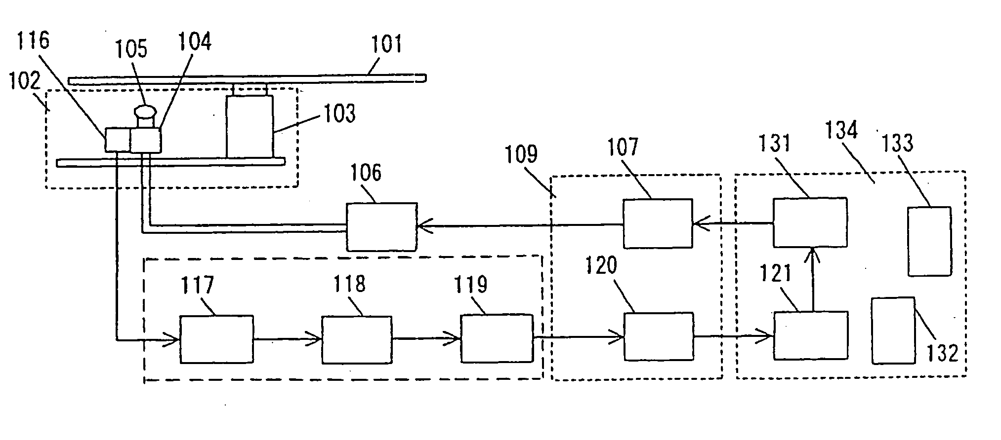
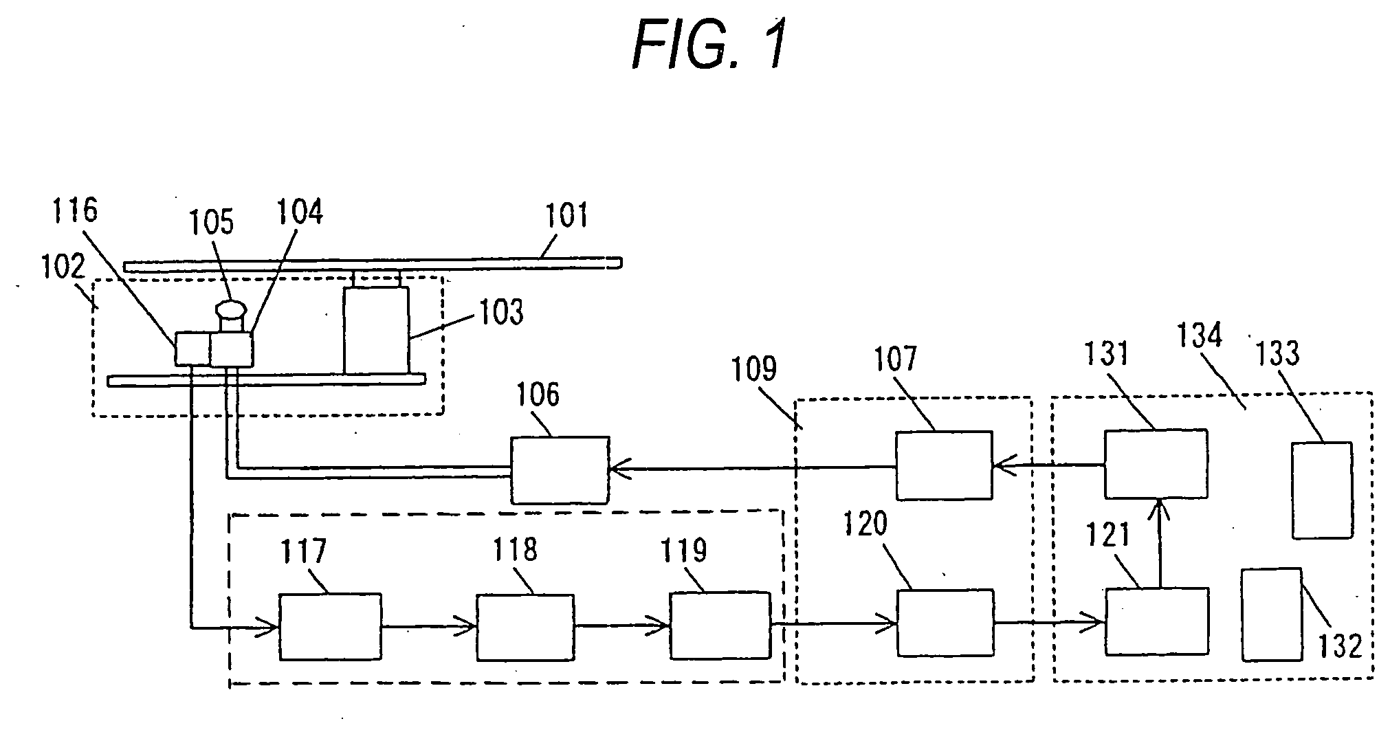
[0038]FIG. 1 is a block diagram of tilt control and focus control in an optical disk apparatus in an embodiment of the invention. Referring to FIG. 1, reference numeral 101 represents an optical disk; reference numeral 102 represents a pickup module; reference numeral 103 represents a spindle motor; reference numeral 104 represents a focus drive coil; reference numeral 105 represents an objective lens; reference numeral 106 represents a reflected light receiving unit; reference numeral 117 represents a reflected light calculation unit; reference numeral 118 represents a reflected light detection unit; reference numeral 119 represents a reflected light A-D conversion unit; reference numeral 120 represents a reflected light A-D-converted value calculation unit; reference numeral 121 represents a reflected light A-D-converted value comparison unit; reference numeral 131 represents a calculation unit which calculates tilt values and focus values; reference numeral 107 represents a focus...


PUM

PropertyMeasurementUnit
temperatureaaaaaaaaaa
operating frequencyaaaaaaaaaa
temperatureaaaaaaaaaa

Abstract

During recording with an optical disk apparatus, an objective lens is moved toward the inner circumference and outer circumference of an optical disk in the radial direction thereof and also moved upward and downward, and the quantity of reflected light is measured at that time. Quantities of reflected light are determined taking advantage of the characteristic of laser heat that it is most efficiently used to provide the smallest quantity of reflected light when the relationship between the optical disk surface and the objective lens is closest to perpendicularity and when they are at a distance at which the point in focus is most closely approached. An optimum tilt value and focus position are learned from the result of the determination to allow operations to be performed at the optimum tilt and the optimum position of the point in focus.

Description

BACKGROUND OF THE INVENTION [0001] The present invention relates to an optical disk apparatus for recording and reproducing information in and from an optical disk and a method of recording with an optical disk apparatus in which a relationship between an optical disk and a tilt and a focus offset of an objective lens of an optical pickup is controlled. [0002] An optical disk cannot be formed with a perfect circular configuration that is completely flat and concentric because of limitations on processes for forming the optical disk. That is, optical disks in the market include optical disks having a center hole that is off the center and optical disks having a warp at the outer circumference thereof. Recently, there are media referred to as printable media on which printing can be performed on a label surface thereof using an inkjet printer. A dedicated material to allow printing using an inkjet printer is applied to the label surface of a printable medium. The material deforms a po...

Claims


Application Information

Patent Timeline
Patent Type & Authority Applications(United States)
IPC IPC(8): G11B7/00G11B7/095G11B7/09
CPCG11B7/0956G11B7/0945
Inventor IWASAKI, SATOSHIMATSUMOTO, SHINJIFUJISHIMA, HIDEYUKI
Owner PANASONIC CORP
Why Eureka
Try Eureka