
Method for manufacturing spectroscopy module, and spectroscopy module

a technology of spectroscopy module and manufacturing method, which is applied in the direction of optical radiation measurement, paper/cardboard containers, instruments, etc., can solve the problems of degrading the reliability of the spectroscopy module, and achieve the effect of improving reliability and easy production

Inactive Publication Date: 2011-09-27
HAMAMATSU PHOTONICS KK
View PDF38 Cites 1 Cited by
  • Summary
  • Abstract
  • Description
  • Claims
  • Application Information

AI Technical Summary

Benefits of technology

The present invention provides a method for manufacturing a highly reliable spectroscopy module. The method includes attaching an incident slit portion and a diode to a supporting body, with a resin layer formed between the diode and the light detecting element to improve the fixing strength. The light detecting element is electrically connected to the wiring on the supporting body using face-down bonding, and a second resin layer is formed to prevent the light from being refracted or diffused. The second resin layer is composed of a material that matches the index of the supporting body higher than the first resin layer. The method also includes using a guide portion to facilitate the formation of the resin layers and ensuring the proper positioning of the light detecting element. The resulting spectroscopy module has improved reliability.

Problems solved by technology

However, in the spectroscopy module described in Patent Document 1, when the incident slit portion and the diode are attached to the supporting body, the relative positional relationship between the incident slit portion and the diode may deviate, thereby degrading the reliability of the spectroscopy module.

Method used


Image

  • Method for manufacturing spectroscopy module, and spectroscopy module
  • Method for manufacturing spectroscopy module, and spectroscopy module
  • Method for manufacturing spectroscopy module, and spectroscopy module

Examples


Embodiment Construction

[0021]Hereinafter, preferred embodiments of the present invention will be described in detail with reference to the drawings. In addition, the same or corresponding portions in the respective drawings are denoted by the same reference numerals, and overlapping descriptions thereof will be omitted.

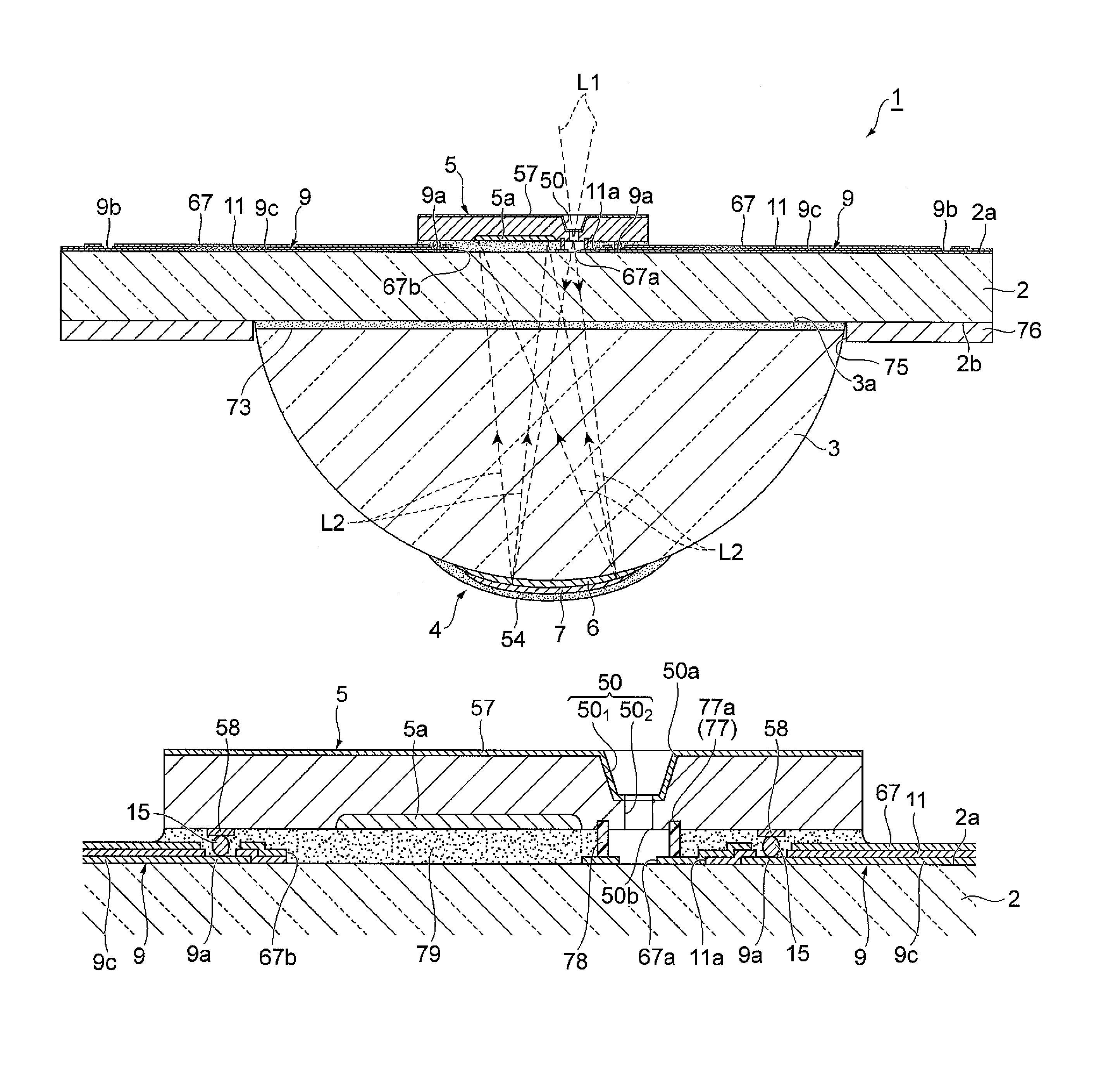
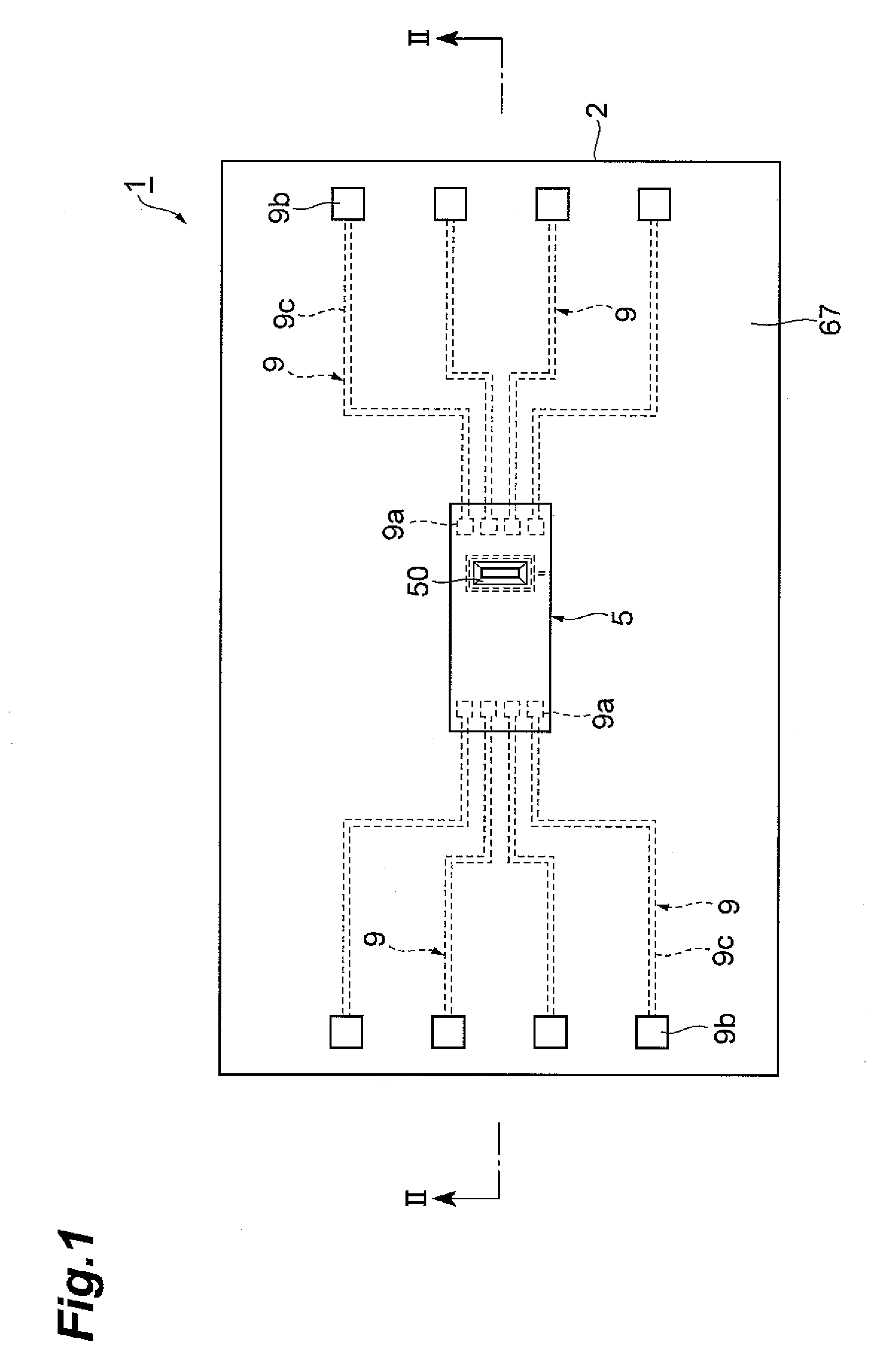
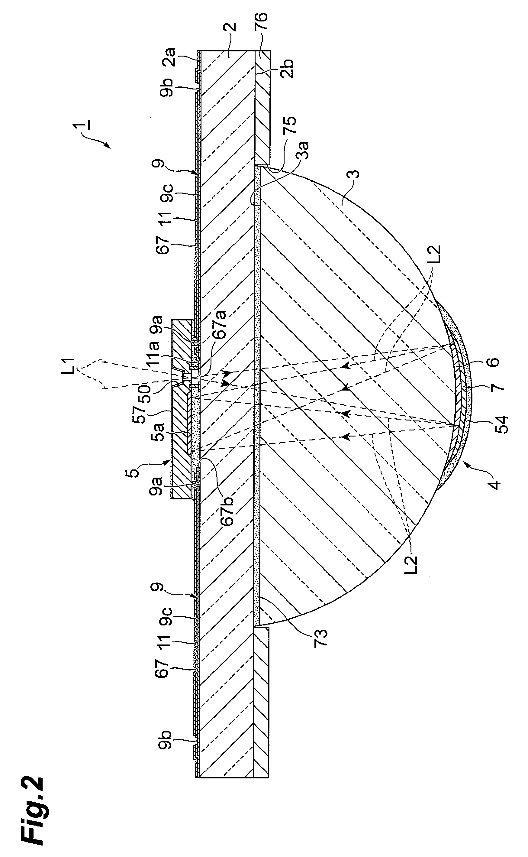
[0022]FIG. 1 is a plan view of a spectroscopy module as one embodiment according to the present invention, and FIG. 2 is a cross sectional view taken along the line II to II shown in FIG. 1. As shown in FIG. 1 and FIG. 2, a spectroscopy module 1 is provided with a substrate (body portion) 2 through which a light L1 made incident from a side of a front plane (predetermined plane) 2a is allowed to transmit, a lens portion (body portion) 3 through which the light L1 made incident into the substrate 2 is allowed to transmit, a spectroscopic portion 4 that disperses the light L1 made incident into the lens portion 3 to reflect the light toward the front plane 2a, and a light detecting element 5 ...


PUM

PropertyMeasurementUnit
thicknessaaaaaaaaaa
widthaaaaaaaaaa
lengthaaaaaaaaaa

Abstract

In a spectroscopy module 1, a light detecting element 5 having a light passing hole 50 is used. Therefore, it is possible to prevent the relative positional relationship between the light passing hole 50 and a light detecting portion 5a of the light detecting element 5 from deviating. Moreover, the light detecting element 5 is electrically connected to a wiring 9 formed on a front plane 2a of a substrate 2 by face-down bonding, and a resin layer 79 is formed as an underfill resin between the substrate 2 and the light detecting element 5. Therefore, it is possible to improve the fixing strength between the substrate 2 and the light detecting element 5. Additionally, before the resin layer 79 is formed, a resin layer 78 is formed along a guide portion 77 that surrounds the passing hole 50. Thus, the resin layer 79 is prevented from penetrating into the light passing hole 50, which makes it possible to make a light be appropriately incident into the substrate 2.

Description

BACKGROUND OF THE INVENTION[0001]1. Field of the Invention[0002]The present invention relates to a method for manufacturing a spectroscopy module for dispersing light to detect the light and spectroscopy module.[0003]2. Related Background of the Invention[0004]There is known such a conventional spectroscopy module described in, for example, Japanese Published Unexamined Patent Application No. H04-294223 (Patent Document 1), Japanese Published Unexamined Patent Application No. 2004-354176 (Patent Document 2), and Japanese Published Unexamined Patent Application No. 2003-243444 (Patent Document 3). Patent Document 1 has described a spectroscopy module which is provided with a supporting body through which light is allowed to transmit, an incident slit portion through which light is made incident into the supporting body, a concave diffraction grating that disperses the light made incident into the supporting body to reflect the light, and a diode that detects the lights dispersed and ...

Claims


Application Information

Patent Timeline
Patent Type & Authority Patents(United States)
IPC IPC(8): G01J3/28
CPCG01J3/02G01J3/0202G01J3/0208G01J3/0243G01J3/0259G01J3/04G01J3/18G01J3/2803G01J3/0262Y10T29/49826Y10T29/49895Y10T156/10
Inventor SHIBAYAMA, KATSUMISUZUKI, TOMOFUMI
Owner HAMAMATSU PHOTONICS KK
Learn More