Spectroscopy module

a technology of spectroscopy module and spectroscopy beam, which is applied in the field of spectroscopy modules, can solve problems such as degrading the reliability of spectroscopy modules, and achieve the effects of reducing the stress generated on the light detecting element, preventing the relative position relationship, and improving reliability

Inactive Publication Date: 2011-09-06
HAMAMATSU PHOTONICS KK
View PDF39 Cites 5 Cited by
  • Summary
  • Abstract
  • Description
  • Claims
  • Application Information

AI Technical Summary

Benefits of technology

[0006]The present invention has been achieved in consideration of the above-described circumstances, and an object of the present invention is to provide a highly reliable spectroscopy module.
[0008]In the spectroscopy module, the light passing hole through which a light advancing to the spectroscopic portion passes is formed in the light detecting element. Therefore, it is possible to prevent the relative positional relationship between the light passing hole and the light detecting portion of the light detecting element from deviating. Moreover, the light detecting element is attached to the predetermined plane of the body portion via the optical resin adhesive. Thus, it is possible to reduce a stress generated onto the light detecting element due to a thermal expansion difference between the light detecting element and the body portion. Additionally, the part of the light incident opening of the light passing hole is covered with the light transmissive plate. Thus, for example, when the light detecting element is attached to the predetermined plane of the body portion via the optical resin adhesive, the part which is not covered with the light transmissive plate serves as an outgassing portion, to allow the optical resin adhesive to penetrate into the light passing hole, and the light incident side surface of the optical resin adhesive becomes a substantially flat plane in the light passing hole. Therefore, it is possible to make a light appropriately incident into the body portion. Therefore, according to the spectroscopy module, it is possible to improve the reliability.
[0009]In the spectroscopy module according to the present invention, the light passing hole is preferably formed so that the light incident opening includes the light emitting opening of the light passing hole when viewed from a direction of its center line, and the light transmissive plate preferably covers a part of the light incident opening so as to include the light emitting opening when viewed from the direction of the center line. In accordance with this configuration, the light emitted from the light emitting opening of the light passing hole passes through the light transmissive plate and the light incident side surface of the optical resin adhesive made to be a substantially flat plane by the light transmissive plate, which makes it possible to make the light approximately incident into the body portion.
[0010]In the spectroscopy module according to the present invention, a light absorbing layer having a first light passing portion through which the light advancing to the spectroscopic portion passes, and a second light passing portion through which the lights advancing to the light detecting portion of the light detecting element pass, is preferably formed on the predetermined plane. In this case, because stray light is prevented from being generated and stray light is absorbed by the light absorbing layer, it is possible to prevent stray light from being made incident into the light detecting portion of the light detecting element.

Problems solved by technology

However, in the spectroscopy module described in Patent Document 1, when the incident slit portion and the diode are attached to the supporting body, the relative positional relationship between the incident slit portion and the diode may deviate, thereby degrading the reliability of the spectroscopy module.

Method used


Image

  • Spectroscopy module
  • Spectroscopy module
  • Spectroscopy module

Examples


Embodiment Construction

[0018]Hereinafter, a detailed description will be given to preferred embodiments of the present invention by referring to the drawings. It is noted that in the individual drawings, the same reference letters or numerals are given to the same and corresponding parts, with overlapping description omitted.

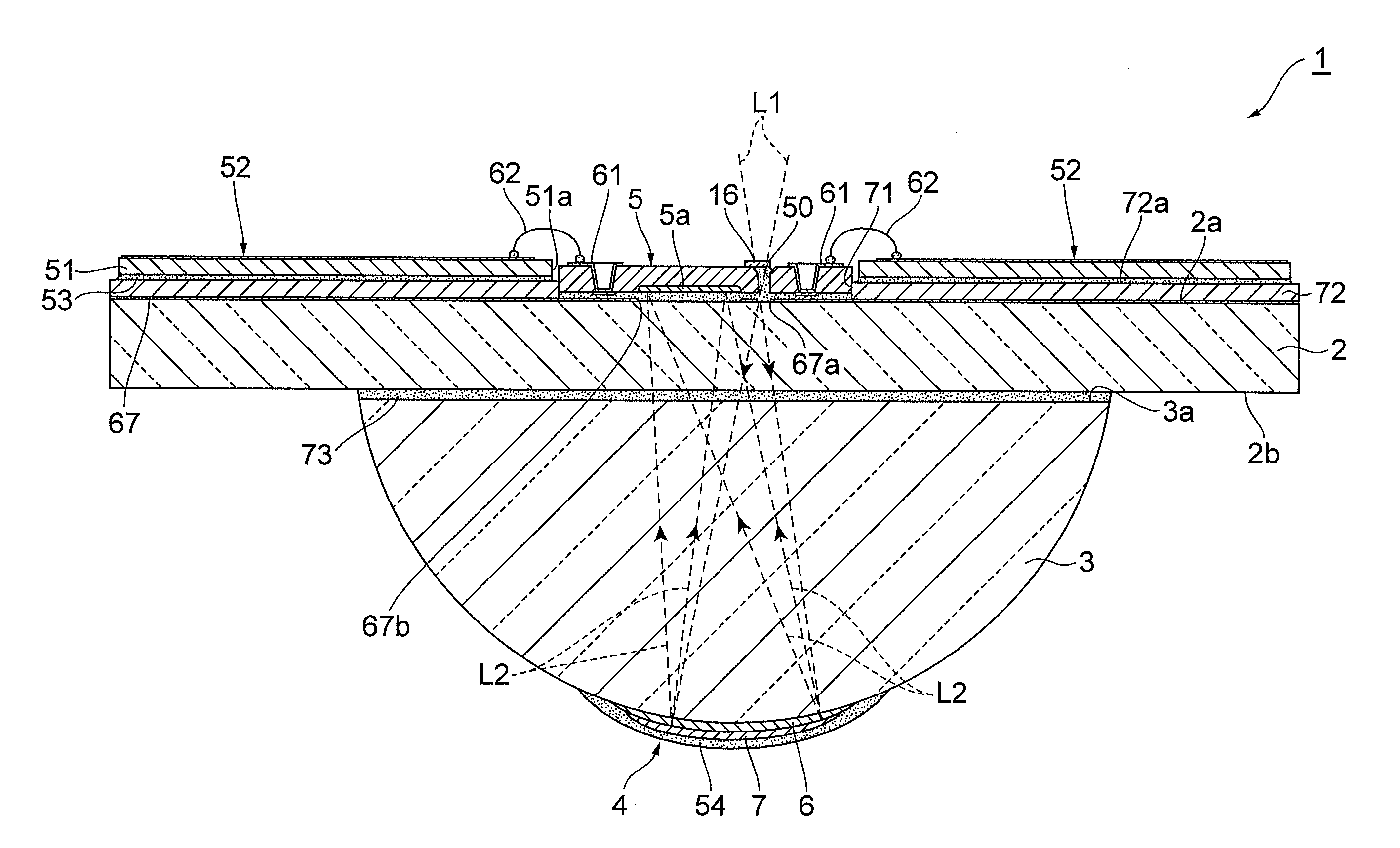
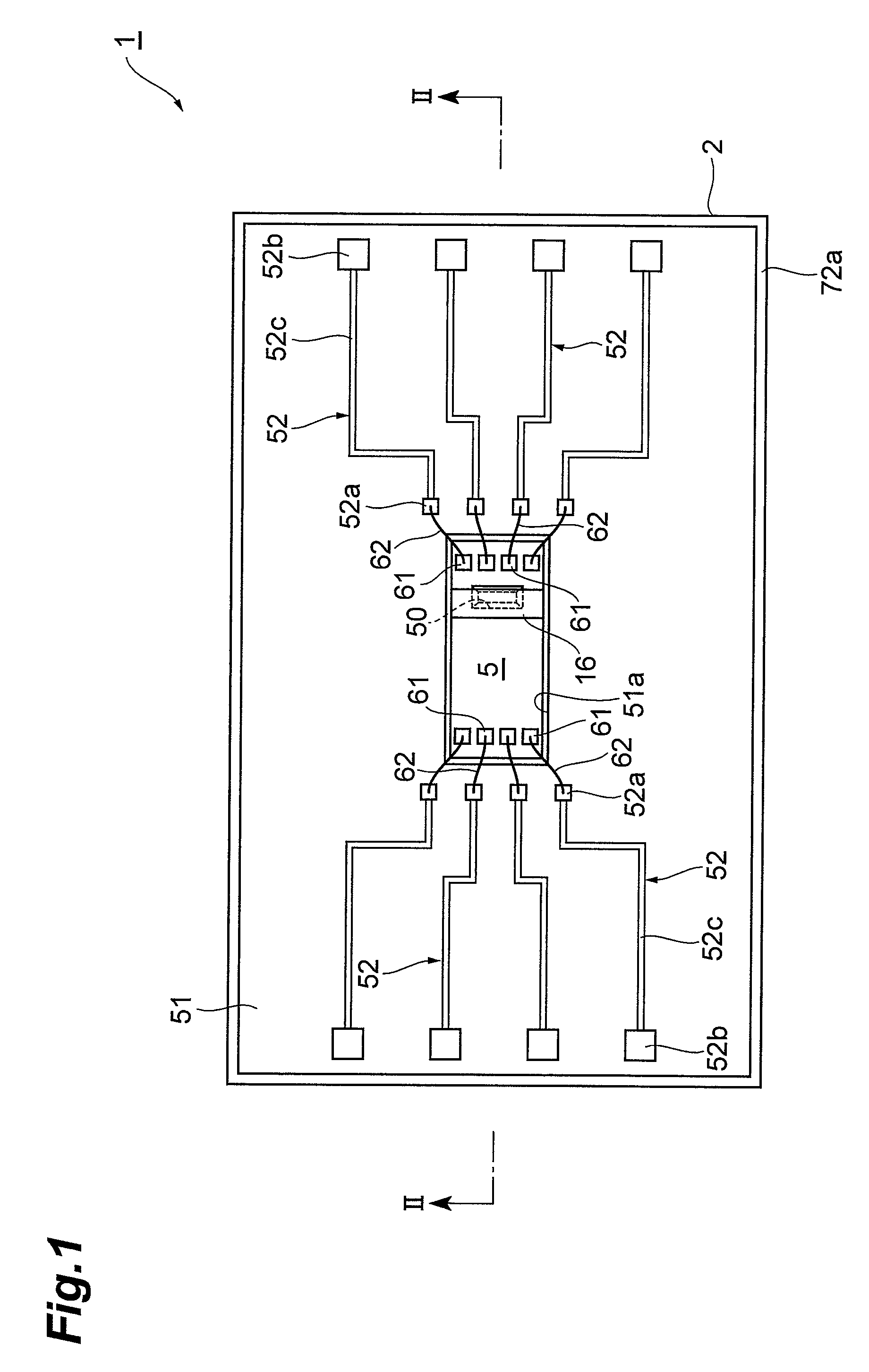
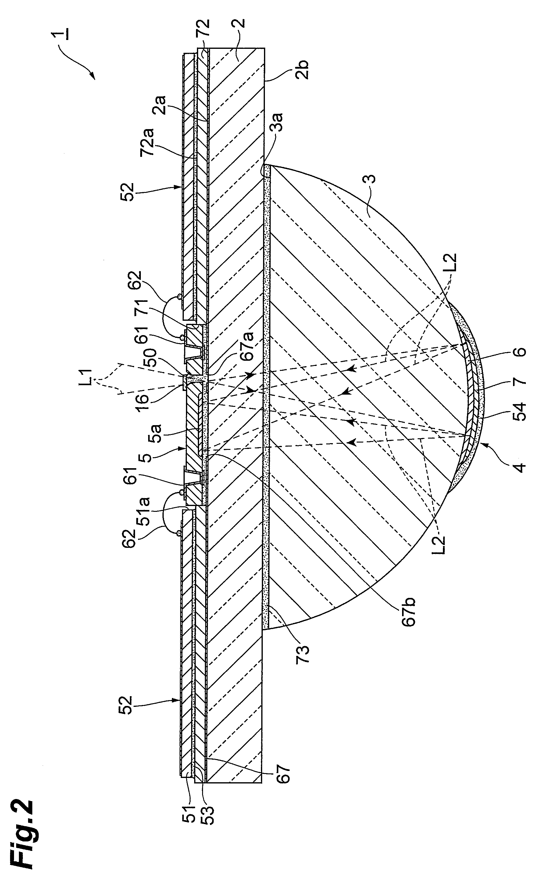
[0019]FIG. 1 is a plan view of a spectroscopy module as one embodiment according to the present invention, and FIG. 2 is a cross sectional view taken along the line II to II shown in FIG. 1. As shown in FIG. 1 and FIG. 2, a spectroscopy module 1 is provided with a substrate (body portion) 2 through which a light L1 made incident from a side of a front plane (predetermined plane) 2a is allowed to transmit, a lens portion (body portion) 3 through which the light L1 made incident into the substrate 2 is allowed to transmit, a spectroscopic portion 4 that disperses the light L1 made incident into the lens portion 3 to reflect the light toward the front plane 2a, and a light detecting elem...


PUM


Abstract

In a spectroscopy module 1, a light passing hole 50 through which a light L1 advancing to a spectroscopic portion 4 passes is formed in a light detecting element 5. Therefore, it is possible to prevent the relative positional relationship between the light passing hole 50 and a light detecting portion 5a of the light detecting element 5 from deviating. Moreover, the light detecting element 5 is bonded to a front plane 2a of a substrate 2 with an optical resin adhesive 63. Thus, it is possible to reduce a stress generated onto the light detecting element 5 due to a thermal expansion difference between the light detecting element 5 and the substrate 2. Additionally, the light transmissive plate 16 covers a part of a light incident opening 50a. Thus, a light incident side surface 63a of the optical resin adhesive 63 becomes a substantially flat plane in the light passing hole 50. Therefore, it is possible to make the light L1 appropriately incident into the substrate 2.

Description

BACKGROUND OF THE INVENTION[0001]1. Field of the Invention[0002]The present invention relates to a spectroscopy module for dispersing light to detect the light.[0003]2. Related Background of the Invention[0004]There is known such a conventional spectroscopy module described in, for example, Japanese Published Unexamined Patent Application No. H04-294223 (Patent Document 1) and Japanese Published Unexamined Patent Application No. 2004-354176 (Patent Document 2). Patent Document 1 has described a spectroscopy module which is provided with a supporting body through which light is allowed to transmit, an incident slit portion through which light is made incident into the supporting body, a concave diffraction grating that disperses the light made incident into the supporting body to reflect the light, and a diode that detects the lights dispersed and reflected by the concave diffraction grating.SUMMARY OF THE INVENTION[0005]However, in the spectroscopy module described in Patent Documen...

Claims


Application Information

Patent Timeline
Patent Type & Authority Patents(United States)
IPC IPC(8): G01J3/28
CPCG01J3/02G01J3/0208G01J3/0243G01J3/0256G01J3/0259G01J3/0286G01J3/0297G01J2003/1213
Inventor SHIBAYAMA, KATSUMISUZUKI, TOMOFUMIYOKINO, TAKAFUMIYOSHIDA, ANNA
Owner HAMAMATSU PHOTONICS KK
Why Eureka
Try Eureka