Imaging device, finder device, method of controlling imaging device, method of controlling finder device, control program for imaging device, and control program for finder device

a technology of imaging device and finder, which is applied in the direction of television system, printer, instrument, etc., can solve the problems of deterioration of pixels, and achieve the effect of preventing burn-in of display device and preventing relative positional relationship

Active Publication Date: 2021-10-12
FUJIFILM CORP
View PDF12 Cites 0 Cited by
  • Summary
  • Abstract
  • Description
  • Claims
  • Application Information

AI Technical Summary

Benefits of technology

[0011]The invention has been accomplished in view of such a situation, and an object of the invention is to provide an imaging device, a finder device, a method of controlling an imaging device, a method of controlling a finder device, a control program for an imaging device, and a control program for a finder device capable of suppressing burn-in of a display device (display) that displays display information on an optical image of a subject observed through an optical finder in a superimposed manner, and preventing a relative positional relationship between a position of display information displayed on the display device and a range, in which imaging is actually performed, from being changed.
[0041]According to the invention, in displaying the display information displayed on the display device on the optical image of the subject observed through the optical finder in a superimposed manner, it is possible to prevent burn-in of the display device, and to prevent the relative positional relationship between the position of the display information displayed on the display device and the range, in which imaging is actually performed, from being changed.

Problems solved by technology

For this reason, while the boundary of the display information is blurred, there are pixels that are constantly displayed, and there is a problem in that the pixels are deteriorated.
On the other hand, in a case where the display information is shifted beyond such a small amount as undetectable by the user with the naked eye, the display information (for example, a visual-field frame, a focus frame, or the like) that should be originally displayed at a prescribed position of the display device is shifted, and there is a problem in that an imaging range to be confirmed by the user through the visual-field frame and a range in which imaging is actually performed are shifted or a target for autofocus adjusted in the focus frame and a target to be actually autofocused are shifted.

Method used


Image

  • Imaging device, finder device, method of controlling imaging device, method of controlling finder device, control program for imaging device, and control program for finder device
  • Imaging device, finder device, method of controlling imaging device, method of controlling finder device, control program for imaging device, and control program for finder device
  • Imaging device, finder device, method of controlling imaging device, method of controlling finder device, control program for imaging device, and control program for finder device

Examples


first embodiment

[0140]Next, a first embodiment of an imaging device that prevents burn-in of the OLED display 218 will be described.

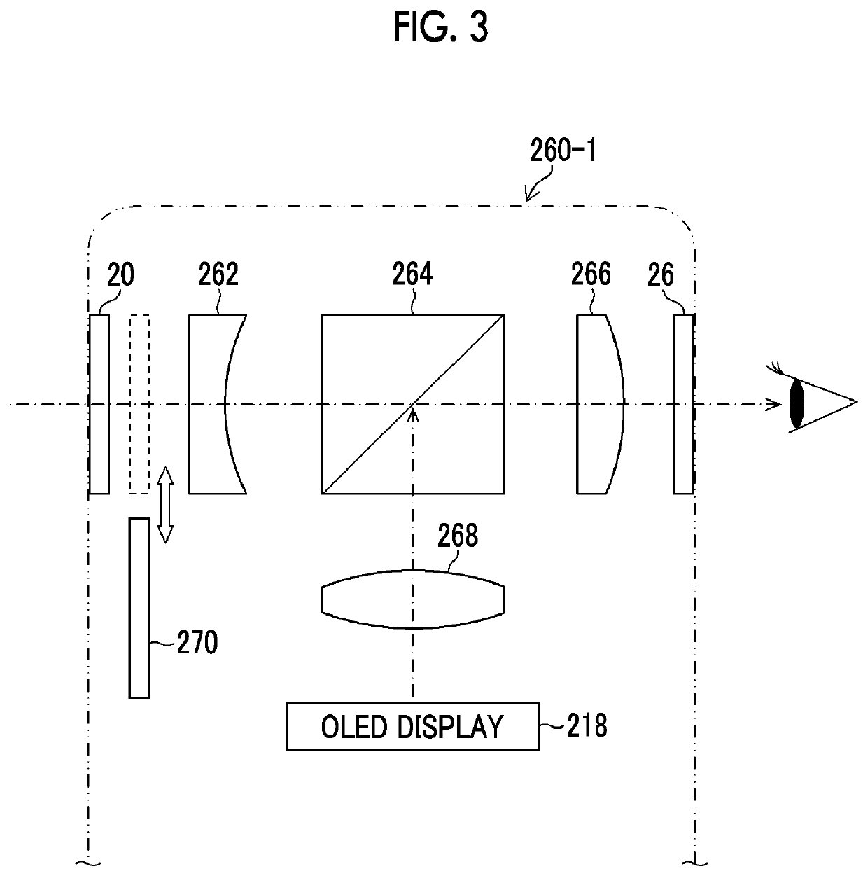
[0141]In a case where the finder device 260-1 (FIG. 3) that is a hybrid view finder is used as an OVF, the visual-field frame 218A and the focus frame 218B (FIG. 5) are displayed on the OLED display 218. In FIG. 5, although the visual-field frame 218A and the focus frame 218B are indicated by thick black lines, the visual-field frame 218A and the focus frame 218B are actually displayed as bright white lines, OLED elements corresponding to the white lines are high in emission brightness, and in a case where light emission is continued for a long time, burn-in occurs.

[0142]The visual-field frame 218A is an index that indicates an imaging range of the image sensor 201, and the focus frame 218B is an index that specifies a target for AF. The focus frame 218B can be moved to an arbitrary position through user setting according to a position of the subject to be focused; how...

second embodiment

[0153]FIG. 7 is a block diagram showing the internal configuration of an imaging device of a second embodiment that prevents burn-in of the OLED display 218. The portions common to the internal configuration of the imaging device shown in FIG. 4 are represented by the same reference numerals, and detailed description thereof will not be repeated.

[0154]The second embodiment shown in FIG. 7 is different from the first embodiment in that the vibration-proof mechanism 209 and the camera shake detection unit 234 are not provided in the camera body 200-2, and a vibration-proof mechanism 117 and a camera shake detection unit 170 are provided in an interchangeable lens 100-2.

[0155]A vibration-proof device of the second embodiment is constituted of the vibration-proof mechanism 117, the camera shake detection unit 170, and the lens-side CPU 120 (or a dedicated shake controller) functioning as a shake controller.

[0156]The camera shake detection unit 170 includes a gyro sensor like the camera ...

third embodiment

[0165]FIG. 8 is a front view of an image sensor 201 used in describing a third embodiment that prevents burn-in of the OLED display 218.

[0166]In FIG. 8, a circle indicated by a broken line is an image circle where a subject image is formed on the image sensor 201 by the imaging optical system 102, and there is an effective pixel region 201A of the image sensor 201 in the image circle. Pixels in the effective pixel region 201A are pixels that can be used in imaging.

[0167]Inside the effective pixel region 201A, there is an imaging pixel region 201B of a captured image to be actually recorded. The number of recorded pixels of a captured image using all pixels of the imaging pixel region 201B becomes a maximum image size (for example, 4896×3264). In general, the effective pixel region 201A is greater than the imaging pixel region 201B, and there is a marginal portion that is not used in imaging.

[0168]In the third embodiment, an image cutout unit (the image sensor controller 202 that is ...


PUM


Abstract

Provided are an imaging device, a finder device, a method of controlling an imaging device, a method of controlling a finder device, a control program for an imaging device, and a control program for a finder device capable of preventing burn-in of a display device that displays display information on an optical image of a subject observed through an optical finder in a superimposed manner, and preventing a relative positional relationship between a position of the display information displayed on the display device and a range, in which imaging is actually performed, from being changed.Display information, such as a visual-field frame, displayed at a prescribed position of an OLED display (218) is moved on the OLED display (218), and burn-in of the OLED display (218) is prevented. An imaging range of an image sensor (201) is moved corresponding to movement of the display information, and a relative positional relationship between a position of the display information displayed on the optical image of the subject observed through the optical finder in a superimposed manner and a range to be actually imaged is prevented from being changed.

Description

CROSS-REFERENCE TO RELATED APPLICATIONS[0001]The present application is a Continuation of PCT International Application No. PCT / JP2018 / 039708 filed on Oct. 25, 2018 claiming priority under 35 U.S.C. § 119(a) to Japanese Patent Application No. 2017-209215 filed on Oct. 30, 2017. Each of the above applications is hereby expressly incorporated by reference, in its entirety, into the present application.BACKGROUND OF THE INVENTION1. Field of the Invention[0002]The present invention relates to an imaging device, a finder device, a method of controlling an imaging device, a method of controlling a finder device, a control program for an imaging device, and a control program for a finder device, and in particular, to a technique for preventing burn-in of a display device to be used in a finder device.2. Description of the Related Art[0003]In the related art, a finder device in which a frame (bright frame) indicating an imaging range displayed on a display unit and display information, such...

Claims


Application Information

Patent Timeline
Patent Type & Authority Patents(United States)
IPC IPC(8): H04N5/232
CPCH04N5/2327H04N5/23254H04N5/23296H04N5/232939G03B5/00G03B5/08G03B13/06G03B17/20H04N23/00H04N23/672H04N23/675H04N23/6812H04N23/687H04N23/633H04N23/684H04N23/69H04N23/6811
Inventor AOKI, TAKASHI
Owner FUJIFILM CORP
Why Eureka
Try Eureka