Heat pump system

Active Publication Date: 2016-10-13
DENSO CORP
View PDF3 Cites 44 Cited by
  • Summary
  • Abstract
  • Description
  • Claims
  • Application Information

AI Technical Summary

Benefits of technology

[0010]The heat-medium radiation portion is provided to enable dissipation of the heat included in the heat medium circulating through the heat-medium circulation circuit, into the low-pressure refrigerant. Then, the heat dissipated from the heat medium into the low-pressure refrigerant can defrost the exterior heat exchanger and suppress the frost formation of the exterior heat exchanger.
[0011]Further, the heat-medium radiation portion dissipates heat included in the heat medium flowing out of the heating heat exchanger into the low-pressure refrigerant, so that the heat included in the heat medium heated by the heat medium-refrigerant heat exchanger can be used t

Problems solved by technology

However, based on the studies by the inventors of the present application, like the heat pump system described in Patent Document 1, a structure that is designed to defrost an exterior heat exchanger with heat supplied from an external heat source, such as a vehicle-mounted electric device, cannot sufficien

Method used


Image

  • Heat pump system
  • Heat pump system
  • Heat pump system

Examples


Example

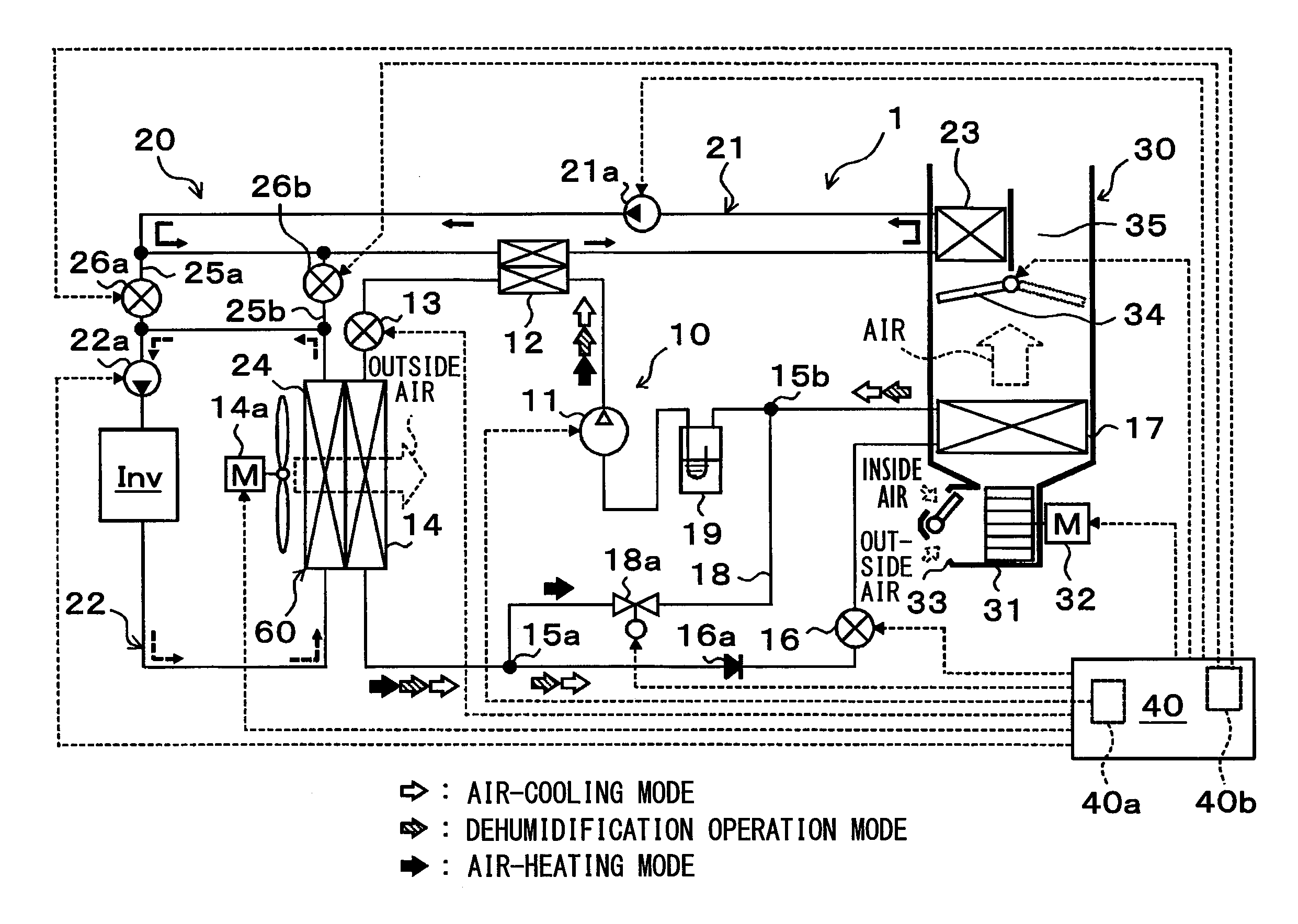
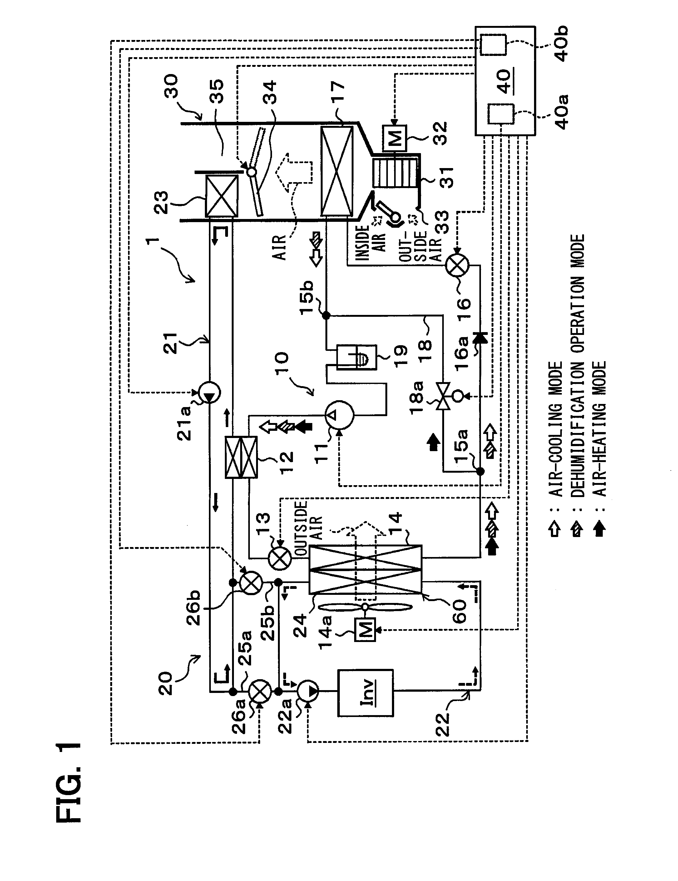
[0038]A first embodiment of the present disclosure will be described below with reference to FIGS. 1 to 4. In this embodiment, a heat pump system 1 according to the present disclosure is applied to a vehicle air conditioner for a so-called hybrid vehicle that obtains the driving force for traveling from both an internal combustion engine (engine) and an electric motor for traveling. The heat pump system 1 in this embodiment serves to heat or cool ventilation air to be blown into a vehicle interior as a space to be air-conditioned in the vehicle air conditioner.

[0039]More specifically, the heat pump system 1 of this embodiment includes a heat pump cycle 10 that is a vapor-compression refrigeration cycle for heating or cooling ventilation air, and a heat-medium circulation circuit 20 for circulation of a coolant as a heat medium (e.g., an ethylene glycol aqueous solution). When intended to heat ventilation air, the coolant is heated by the heat pump cycle 10, and then the ventilation ...

Example

Second Embodiment

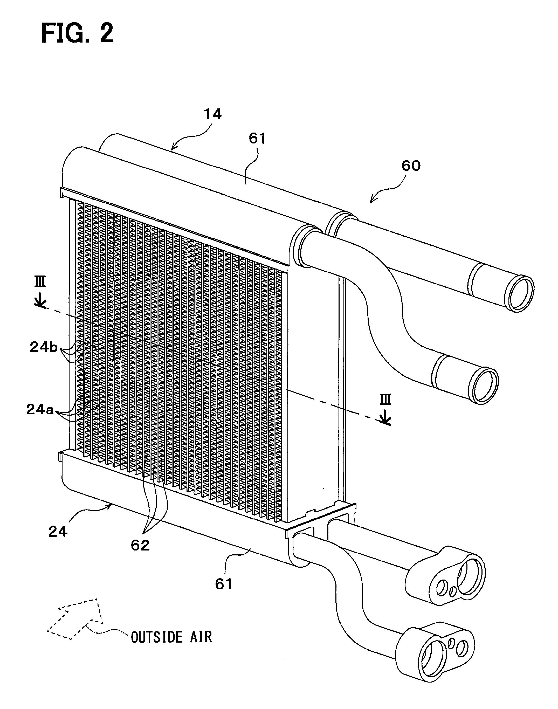
[0192]Although as described in the first embodiment, the exterior heat exchanger 14 and the radiator 24 are integrated together into the heat-exchanger structure 60 by way of example, in this embodiment as shown in the entire configuration diagram of FIG. 5, the exterior heat exchanger 14 and the radiator 24 are individually formed of separate heat exchangers. Referring to FIG. 5, the same or equivalent parts as those described in the first embodiment are designated by the same reference numerals. The same goes for the following figures.

[0193]The exterior heat exchanger 14 of this embodiment is disposed to exchange heat between the refrigerant circulating therethrough and the outside air blown from the blower fan 14a and having passed through the radiator 24. That is, the exterior heat exchanger 14 is disposed downstream of the outside air flow blown from the blower fan 14a, rather than the radiator 24. The structures and operations of other components of the heat p...

Example

Third Embodiment

[0198]In this embodiment, compared to the second embodiment, as shown in the entire configuration diagram of FIG. 6, a low-temperature side coolant-refrigerant heat exchanger 27 is employed, instead of the radiator 24, to exchange heat between the coolant circulating through the heat-medium circulation circuit 20 (specifically, the low-pressure side heat-medium circulation circuit 22) and the low-pressure refrigerant (specifically, the refrigerant flowing out of the exterior heat exchanger 14) by way of example.

[0199]The low-temperature side coolant-refrigerant heat exchanger 27 has the substantially same basic structure as that of the high-temperature side coolant-refrigerant heat exchanger 12. In this embodiment, the low-temperature side coolant-refrigerant heat exchanger 27 configures a heat exchanger for heat-medium radiation that exchanges heat between the low-pressure refrigerant and the coolant flowing out of the heater core 23. The structures of other compone...


PUM


Abstract

A heater core for exchanging heat between a coolant and ventilation air to be blown into a vehicle interior is disposed in a high-pressure side heat-medium circulation circuit that allows for circulation of the coolant heated by a heat pump cycle. A radiator for exchanging heat between at least a part of the coolant flowing out of the heater core and a low-pressure refrigerant in the heat pump cycle is disposed in a low-pressure side heat-medium circulation circuit coupled to the high-pressure side heat-medium circulation circuit. Thus, excessive heat included in the coolant flowing out of the heater core and which is not used to heat the ventilation air can suppress frost formation on an exterior heat exchanger and can also defrost the exterior heat exchanger.

Description

CROSS REFERENCE TO RELATED APPLICATION[0001]The application is based on a Japanese Patent Application 2013-242521 filed on Nov. 25, 2013, the contents of which are incorporated herein by reference in its entirety.FIELD OF THE INVENTION[0002]The present disclosure relates to a heat pump system that heats a fluid to be heated by a heat pump cycle.BACKGROUND ART[0003]Heat pump systems are conventionally known to heat a heating target fluid by heat pump cycles (vapor-compression refrigeration cycles). In the heat pump cycle applied to this kind of system, an exterior heat exchanger serves as an evaporator that evaporates a low-pressure refrigerant by exchanging heat with the outside air. When a refrigerant evaporation temperature at the exterior heat exchanger is decreased to 0° C. or lower, frost formation might occur in the exterior heat exchanger.[0004]Further, the so-called hot gas defrosting is also known as a means for removing frost formed in the exterior heat exchanger in this w...

Claims


Application Information

Patent Timeline
IPC IPC(8): B60H1/00F25B49/02
CPCF25B49/02B60H1/00921F25B2347/02F25B47/02F25B2400/05B60H2001/00961B60H1/32281
Inventor SAKAMOTO, KOTAITOH, SATOSHI
Owner DENSO CORP
Why Eureka
Try Eureka