

Cooling structure of rotor for rotary electric machine, and rotary electric machine
- Summary
- Abstract
- Description
- Claims
- Application Information
AI Technical Summary
Benefits of technology
Problems solved by technology
Method used
Image

Examples
Embodiment Construction
[0019]Hereinafter, example embodiments of the invention will be described in detail with reference to the accompanying drawings. In the description, the specific shapes, materials, numeric values, and directions and the like are merely examples to facilitate understanding of the invention, and may be changed as appropriate according to the use, objective, and specifications and the like. When a plurality of example embodiments or modified examples or the like are included in the description below, appropriate combined usage of the characteristic portions of these is initially assumed.
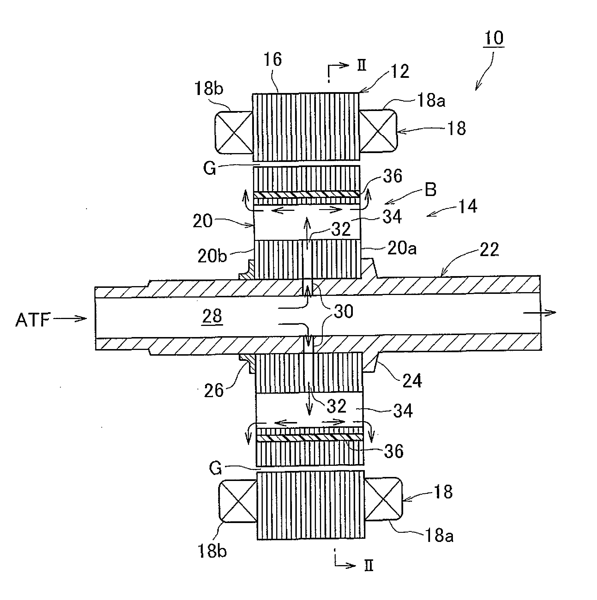
[0020]FIG. 1 is a sectional view along an axial direction of a rotary electric machine 10 that includes a rotor cooling structure according to one example embodiment of the invention. As shown in FIG. 1, the rotary electric machine 10 includes a stator 12 and a rotor 14. A radial gap portion G is provided between the stator 12 and the rotor 14. Note that the term indicating the radial direction, such as...
PUM
 Abstract
Description
Claims
Application Information