

Train power supply cabinet of electric locomotive
A technology for electric locomotives and power supply cabinets, applied to electrical components, output power conversion devices, AC power input to AC power output, etc., can solve problems such as inability to meet electricity demand, ensure normal power supply, and improve output capacity Effect
- Summary
- Abstract
- Description
- Claims
- Application Information
AI Technical Summary
Problems solved by technology
Method used
Image

Examples
Embodiment 1
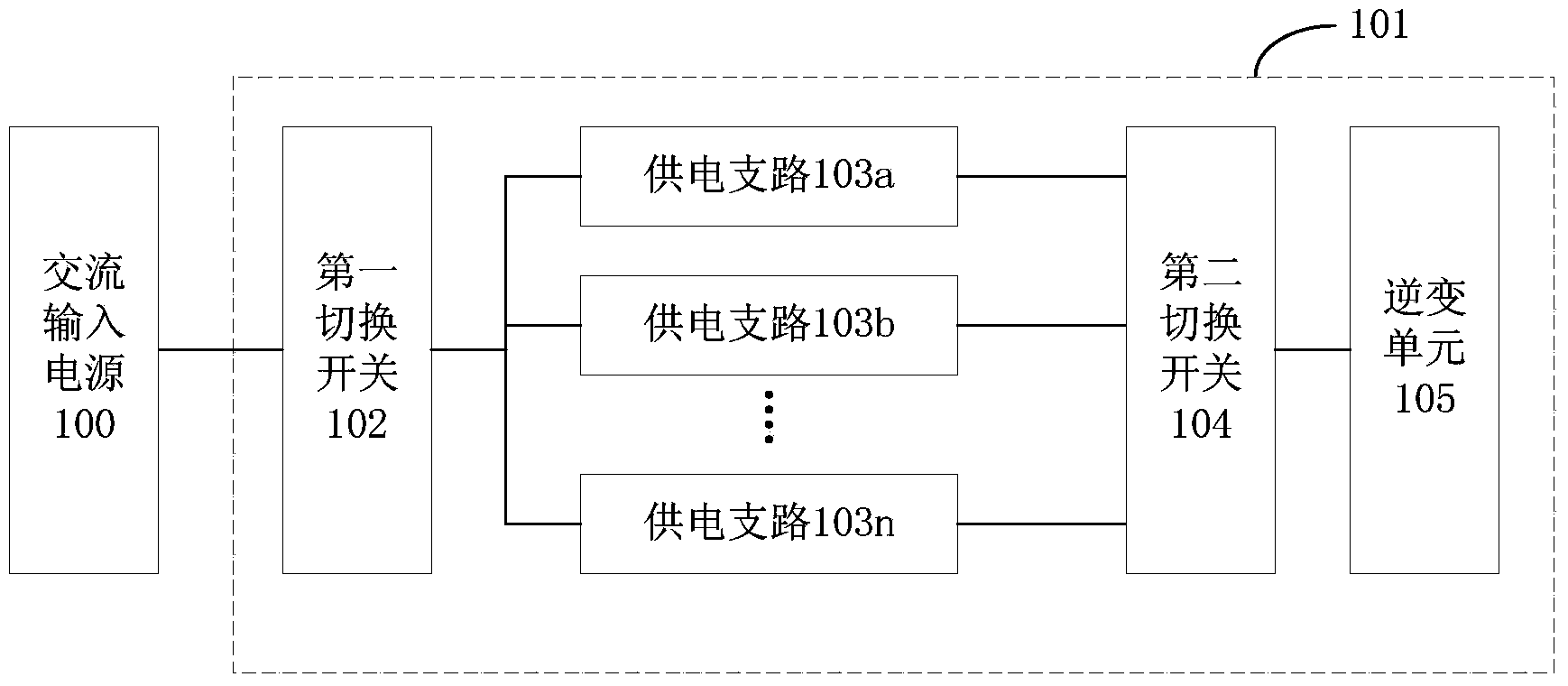
[0033] Aiming at the defect that the existing train power supply cabinets of electric locomotives cannot meet the increasing power consumption requirements of electric loads, the present invention provides a new train power supply cabinet for electric locomotives. figure 1 A schematic structural view of the train power supply cabinet of the electric locomotive provided by this embodiment is shown.
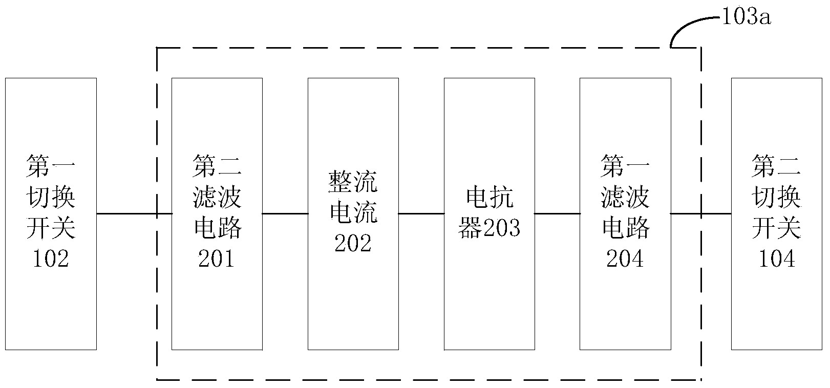
[0034] like figure 1 As shown, the train power supply cabinet 101 provided in this embodiment includes a first switch 102 and at least three power supply branches with the same structure (such as power supply branch 103a, power supply branch 103b, . . . , power supply branch 103n, etc.). Wherein, one end of the first switch 102 is connected to the AC input power source 100 (such as a silicon unit, etc.), and the other end is correspondingly connected to each power supply branch through each port, so as to switch the required power supply branch from each power supply branch. As a ...
Embodiment 2
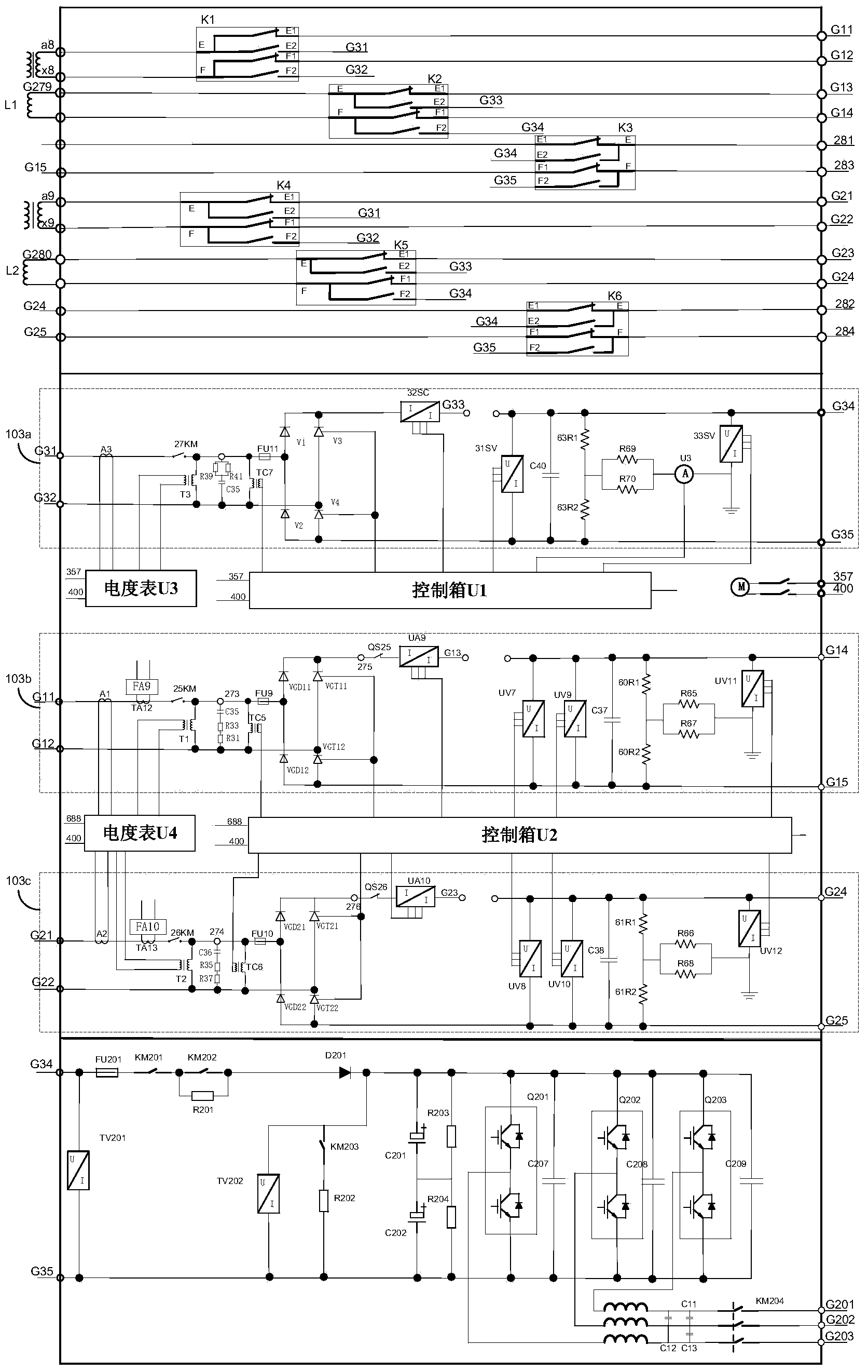
[0048] image 3 It shows the schematic circuit diagram of the train power supply cabinet provided by this embodiment for receiving electric power from trains.
[0049] It can be seen from the figure that the train power supply cabinet provided in this embodiment includes three power supply branches with the same structure, namely the power supply branch 103a, the power supply branch 103b and the power supply branch 103c. In this embodiment, the power supply branch 103a and the power supply branch 103b are used as the default power supply branch, and the power supply branch 103c is used as the backup power supply branch. When the power supply branch 103a or the power supply branch 103b fails, the failed power supply The branch is cut out, and the power supply branch 103c cuts in as the standby power supply branch, thereby ensuring that the power supply branch of the train power supply cabinet is in working state and there are still two roads, so that the performance of the trai...
PUM
 Abstract
Description
Claims
Application Information