Compressor with segmented inner shroud for an axial turbine engine

A turbine engine, engine technology, applied in the direction of engine cooling, engine lubrication, components of pumping devices for elastic fluids, etc., can solve the problems of complex layout, leakage, increased geometric structure restrictions of rectifier non-uniformity, etc., To achieve the effect of output optimization

Active Publication Date: 2018-08-03
SAFRAN AERO BOOSTERS SA
View PDF8 Cites 2 Cited by
  • Summary
  • Abstract
  • Description
  • Claims
  • Application Information

AI Technical Summary

Problems solved by technology

However, this arrangement is complex and heavy
It increases rectifier non-uniformity and geometry constraints
Also, there will be some leakage at the in

Method used


Image

  • Compressor with segmented inner shroud for an axial turbine engine
  • Compressor with segmented inner shroud for an axial turbine engine
  • Compressor with segmented inner shroud for an axial turbine engine

Examples


Embodiment Construction

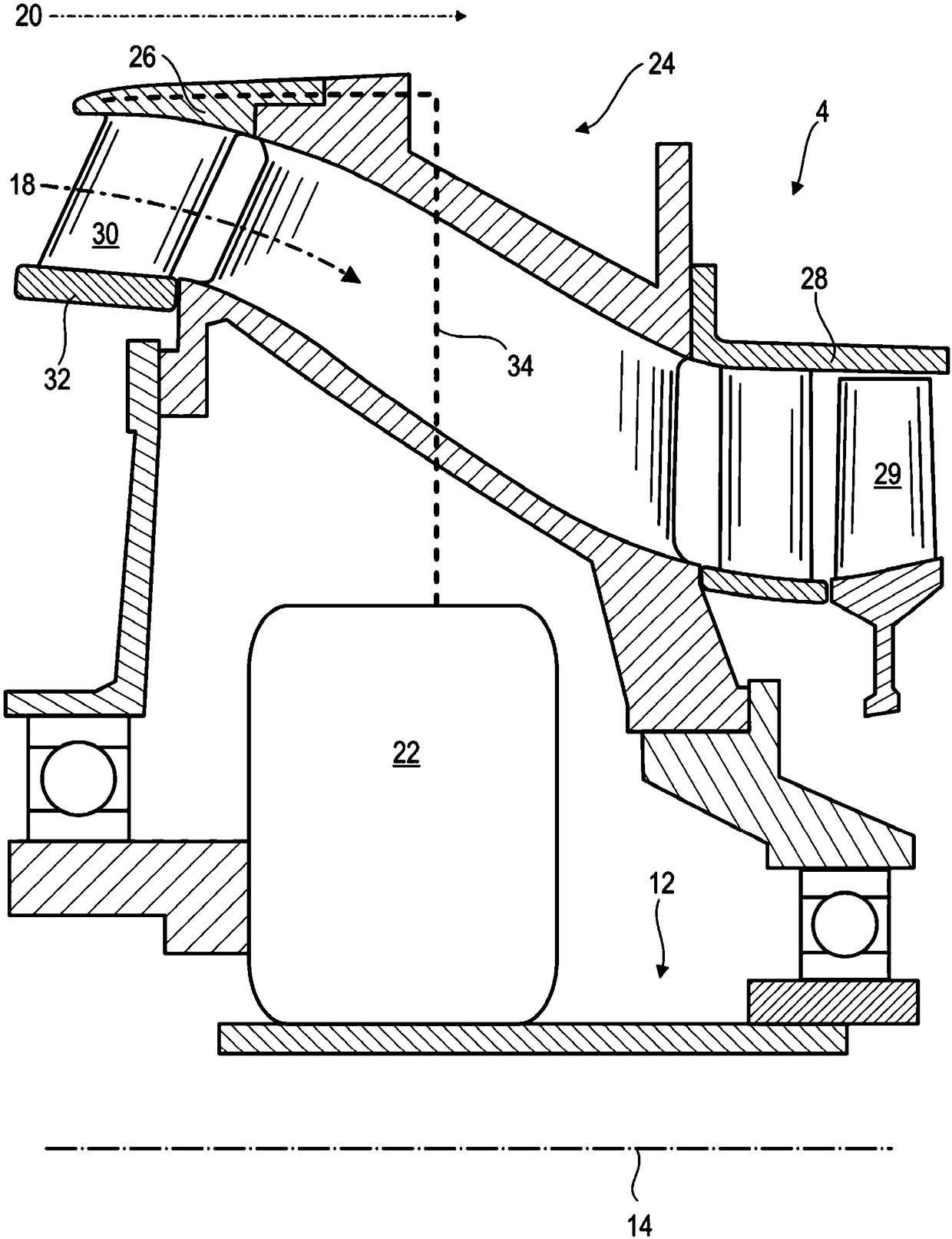
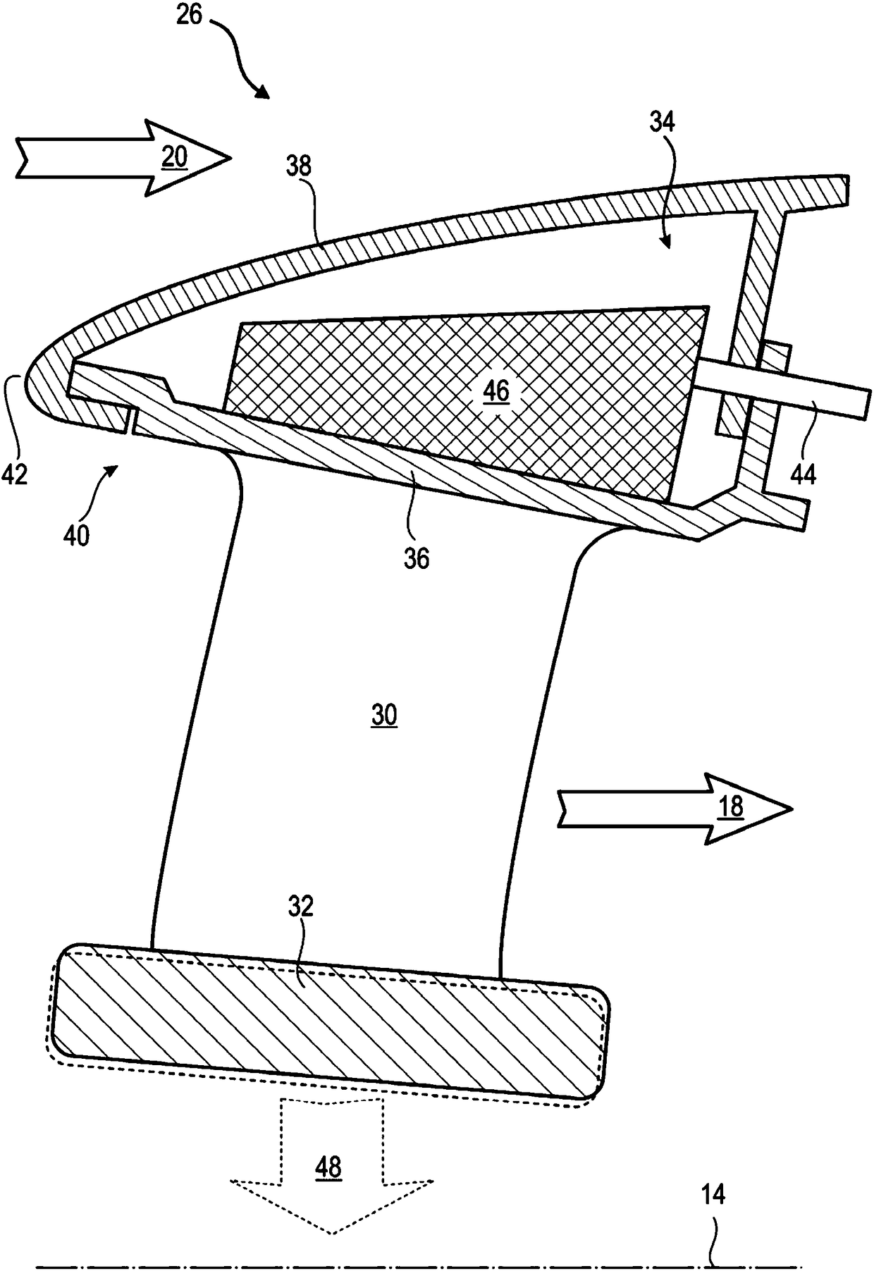
[0044] It should be clearly understood that the invention proposes a turbojet engine with a fan driven by a drive forming a heat source whose heat affects the circumference between the segments of the inner shroud via a cooling and / or lubrication circuit. To the size of the gap, the inner shroud is attached to the stator blades.

[0045] In the following description, the terms "inner" and "outer" refer to an orientation relative to the axis of rotation of the axial turbine engine. Axial corresponds to a direction along the axis of rotation of the turbine engine. Radial is perpendicular to the axis of rotation. Upstream and downstream refer to the main flow directions of flow in a turbine engine.

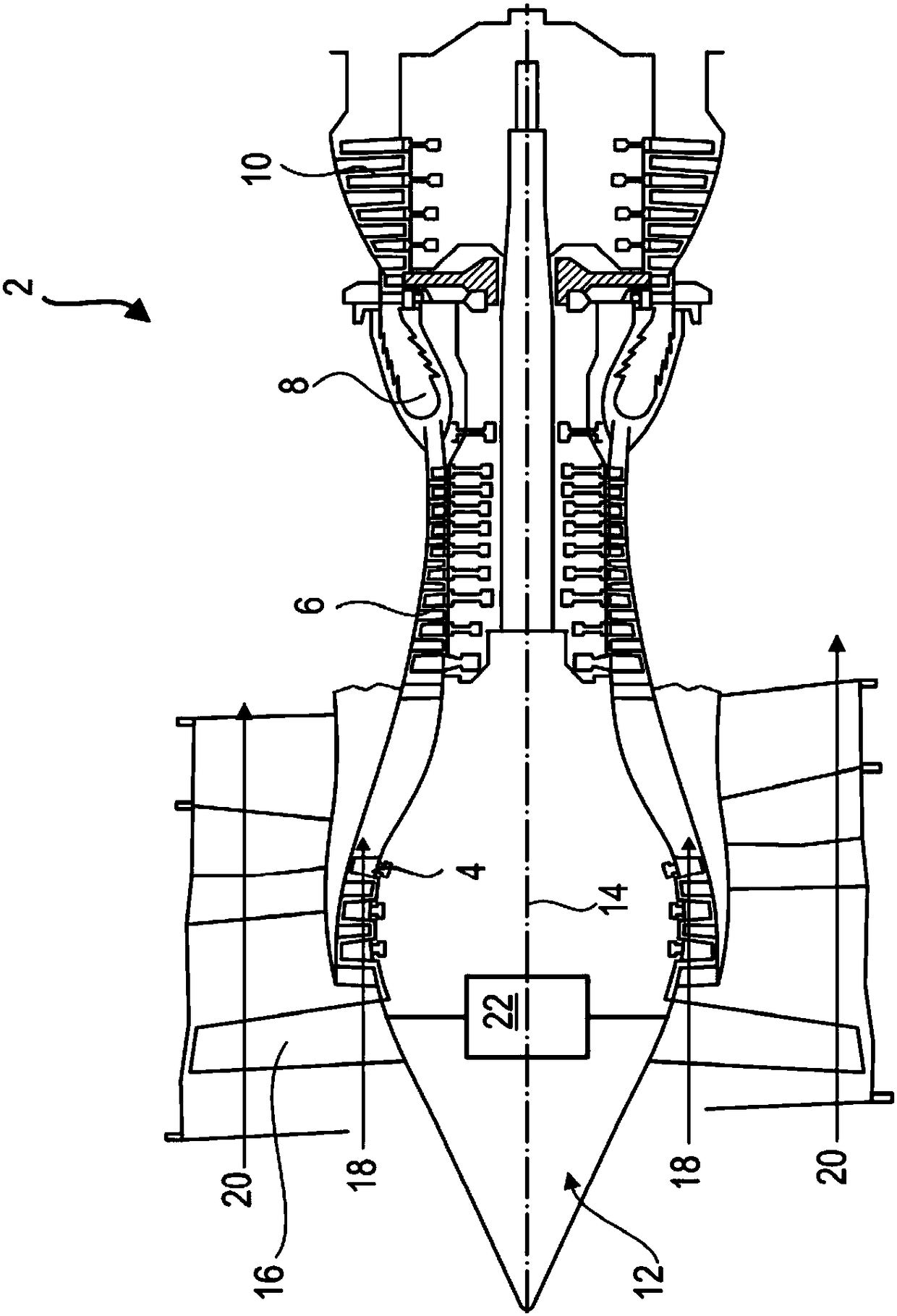
[0046] figure 1 An axial turbine engine 2 is shown in a simplified manner. In this particular case it is a dual flow turbo jet engine. The turbojet engine comprises a first compression stage called low-pressure compressor 4 , a second compression stage called high-pressure compr...


PUM


Abstract

The invention relates to an assembly for a turbojet engine. The assembly comprises an outer shroud (36) and an inner shroud (32) being segmented and comprising circumferential clearances between the segments thereof; an annular row of stator vanes connecting the inner shroud (32) to the outer shroud; a drive with a reduction ratio, which drive is intended to be coupled to a fan; and a loop (34) for cooling and for lubricating the drive, which the loop is configured to heat up at least the outer shroud (36) during the operation of the turbine engine such as to circumferentially reduce the circumferential clearances between the segments. The invention further brings forward a method used for controlling the circumferential clearances between segments of the inner shroud of the turbojet engine.

Description

technical field [0001] The present invention relates to the field of segmented inner shroud seals. More precisely, the invention relates to the sealing between two inner shroud segments of a turbine engine. The invention also relates to an axial turbine engine, in particular an aircraft turbojet or an aircraft turboprop. Background technique [0002] In turbojet engines, compressors with integral vane rotors require the use of a double-shell outer casing structure to allow the installation of a stator. Additionally, the inner shrouds must be separated at an angle. Each rectifier inner shroud then has a cutout or separation. These structures define adjacent segments along the circumference. The separation forms an undesired leak-causing channel. [0003] Document EP 3 018 295 A1 discloses a turbojet engine comprising a low-pressure compressor, a gearbox and a fan. The compressor includes a plurality of rectifiers, each rectifier having annular rows of stator blades conn...

Claims


Application Information

Patent Timeline
IPC IPC(8): F01D25/24F01D25/10F01D9/04F01D11/00
CPCF01D9/041F01D11/00F01D25/10F01D25/24F01D25/246F05D2220/323F05D2300/505F05D2300/603F05D2300/40F01D9/04F01D11/005F01D11/24F01D15/12F01D25/14F01D25/162F02C7/047F02C7/06F02C7/14F04D29/584F05D2300/50212F04D29/542F01D25/02F04D29/083Y02T50/60F01D11/025F01D5/143F05D2300/5021F05D2240/11F05D2240/14F05D2260/40311F05D2260/30
Inventor S.希尔瑙克斯
Owner SAFRAN AERO BOOSTERS SA
Why Eureka
Try Eureka