Image forming apparatus and its control method

Inactive Publication Date: 2005-08-04
CANON KK
View PDF39 Cites 66 Cited by
  • Summary
  • Abstract
  • Description
  • Claims
  • Application Information

AI Technical Summary

Benefits of technology

[0020] The present invention fulfills the above-described and other needs by providing an image forming apparatus and its control method that can implement on-demand fusing with quick rise in temperature by using the upper current (power) limit of a commercial power supply more effectively. In exemplary embodiments, the image forming apparatus includes a rechargeable battery device capable of charging and discharging, and is designed such that a load other than the heating element of a fusing device can receive power

Problems solved by technology

The power supplied from the commercial power supply to the fusing devic

Method used


Image

  • Image forming apparatus and its control method
  • Image forming apparatus and its control method
  • Image forming apparatus and its control method

Examples


first embodiment

100>

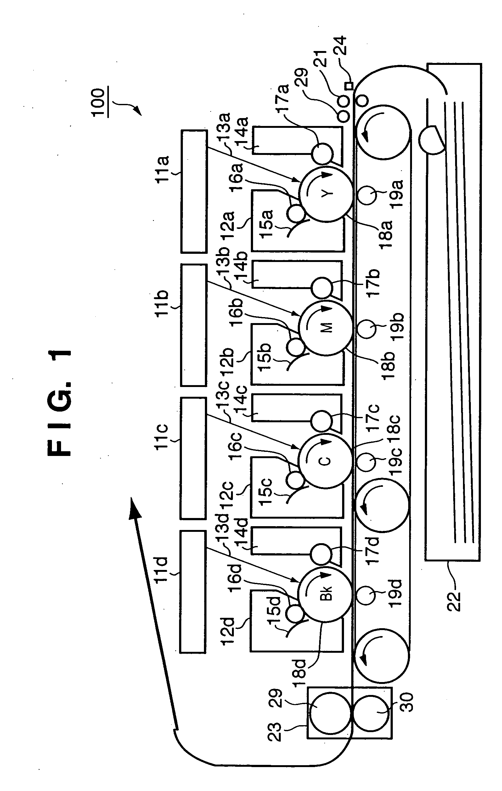
[0053]FIG. 1 is a view showing the schematic arrangement of a laser beam printer 100 according to an embodiment of the present invention. The laser beam printer 100 is a so-called tandem type printer provided with image forming units for the respective color images, i.e., a black image (BK), yellow image (Y), magenta image (M), and cyan image (C).

[0054] Each image forming unit is comprised of a photoconductive drum 18, a primary charger 16 which uniformly charges the photoconductive drum, a scanner unit 11 which forms a latent image on the photoconductive drum, a developing device 14 which develops the latent image into a visual image, a transfer device 19 which transfers the visual image onto a transfer sheet, a cleaning device 15 which removes residual toner from the photoconductive drum, and the like.

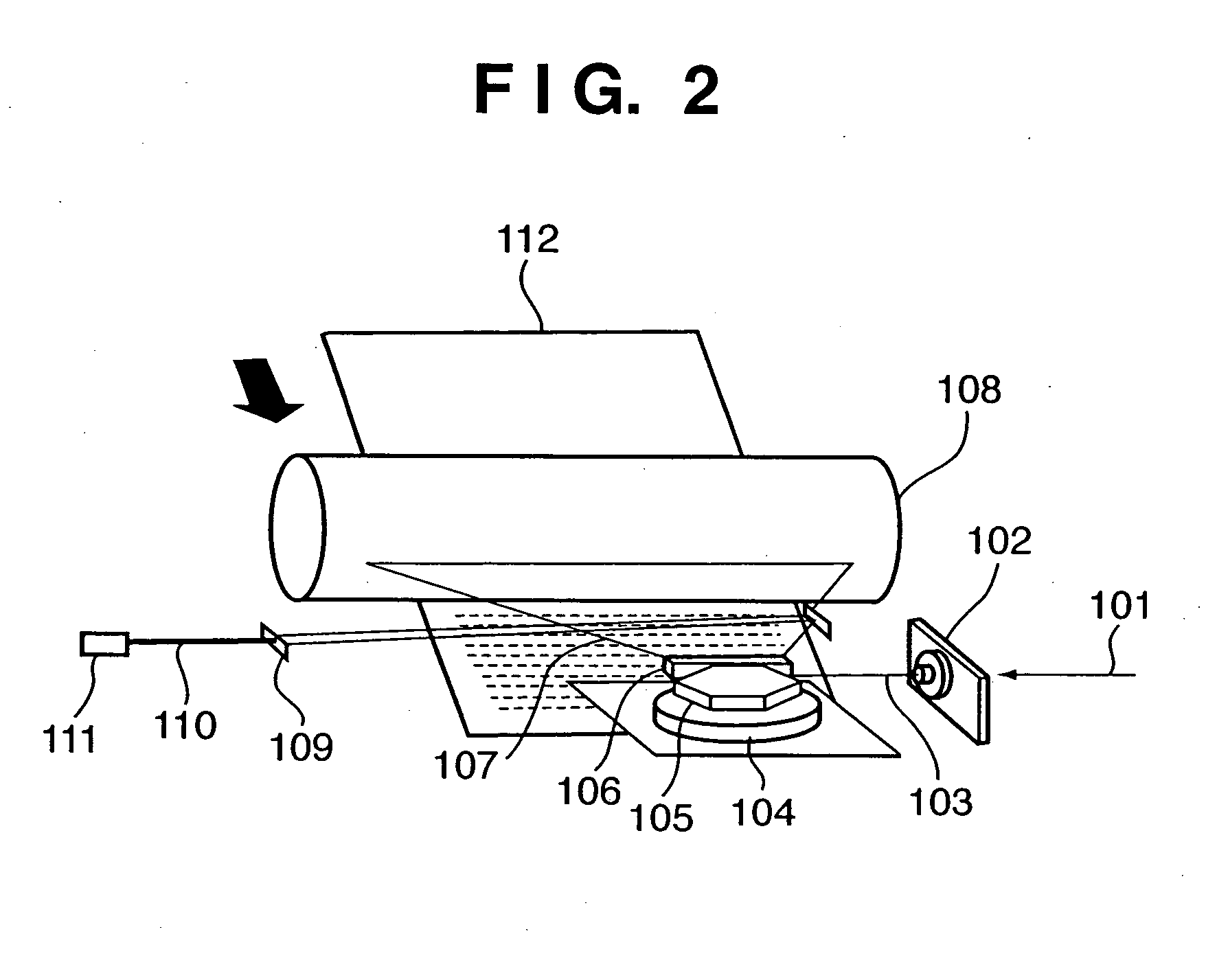
[0055] The arrangement of the scanner unit 11 will be described. FIG. 2 is a view showing the arrangement of the scanner unit 11. Upon reception of an instruction to form an im...

second embodiment

[0121]FIG. 13 is a block diagram showing the arrangement of the power supply control system of a laser beam printer 100 in the second embodiment. This embodiment differs from the first embodiment (FIG. 3) in that a current detection circuit 471 is provided on the input side (primary side) of a switching power supply circuit 470. A current detected by the current detection circuit 471 is a physical quantity corresponding to the power supplied from a commercial power supply 301 to a load 460.

[0122] The current detection circuit 471 detects the root mean square value or mean value of input currents flowing in the switching power supply circuit 470, and transmits the detection value, as, for example, an analog signal, to the A / D port of a CPU (not shown) in an image forming control circuit 316.

[0123] The image forming control circuit 316 changes a reference voltage Vs 326 (FIG. 9) of a fusing control circuit 330 in accordance with the current detection result from the current detectio...

third embodiment

[0144]FIG. 16 is a block diagram showing the arrangement of the power supply control system of a laser beam printer 100 according to the third embodiment. This embodiment differs from the third modification (FIG. 15) to the second embodiment in that a power detection circuit 484 is provided on the input side of a fusing control circuit 330 instead of the input side (primary side) of a switching power supply circuit 470. The power detected by the power detection circuit 484 is power supplied from a commercial power supply 301 to a fusing device 23.

[0145] The power detection circuit 484 detects the root mean square value or mean value of powers on the input side (primary side) of the fusing control circuit 330, and transmits the detection value, as, for example, an analog signal, to the A / D port of the CPU (not shown) in an image forming control circuit 316. While power is supplied from the rechargeable battery device 455, the image forming control circuit 316 changes a reference vol...


PUM


Abstract

There are provided an image forming apparatus which can implement on-demand fusing with quick rise in temperature by using the upper current (power) limit of a commercial power supply more effectively and a control method for the apparatus. This image forming apparatus includes a rechargeable battery device capable of charging and discharging, and is designed such that a load other than the heating element of a fusing device can receive power from the commercial power supply and/or the rechargeable battery device. When printing is to be executed, the temperature of the fusing device is detected by a temperature detection element provided for the fusing device, and the supply of power from the commercial power supply or rechargeable battery device to the load is controlled in accordance with the detected temperature. The power supplied from the commercial power supply to the fusing device is then limited to a limit level corresponding to the control result.

Description

FIELD OF THE INVENTION [0001] The present invention relates to an image forming apparatus and its control method and, more particularly, to an image forming apparatus using an electrophotographic process and a control method. BACKGROUND OF THE INVENTION [0002] An image forming apparatus using an electrophotographic process, e.g., a laser beam printer, comprising a fusing device which thermal-fuses a toner image formed on a printing medium (e.g., a printing sheet or OHP sheet). The heating systems which can be used for this fusing device include several types. Of these types, an electromagnetic induction heating system which induces a current in a fusing roller using a magnetic flux and generates heat using the resultant Joule heat, in particular, can directly cause the fusing roller to generate heat by using the generation of the induced current. This system is advantageous over a fusing unit based on a heated roller system using a halogen lamp as a heat source in terms of achieving...

Claims


Application Information

Patent Timeline
IPC IPC(8): G03G15/00G03G21/00G03G15/20
CPCG03G2215/00983G03G2215/2035G03G15/80G03G15/2039
Inventor KOYAMA, SATORUHANAMOTO, HIDETOSHITAKEUCHI, AKIHIKO
Owner CANON KK
Why Eureka
Try Eureka