Catheter assembly with joinable catheters

a catheter and distal tip technology, applied in the field of catheters, can solve the problems of inability to adapt to the patient's wide variety of sizes, the distance between the distal tips of the catheter is predetermined, and the catheter may not be useful for a wide variety of patients' sizes, so as to avoid discomfort, trauma, or stenosis, and maintain the thickness of the wall. , the effect of decreasing the distance between the distal tips

Inactive Publication Date: 2005-08-04
CUNNINGHAM JON
View PDF3 Cites 51 Cited by
  • Summary
  • Abstract
  • Description
  • Claims
  • Application Information

AI Technical Summary

Benefits of technology

[0012] In one embodiment, the catheter assembly has at least two catheters that are approximately parallel to one another. The at least two catheters are long enough to extend though the subcutaneous tunnel from the exit site to the catheterized blood vessel. The at least two catheters are formed from two independent tubular structures. Each tubular structure has a relatively constant wall thickness and flow cross-section across its length and is used for facilitating simultaneous opposing fluid flow between the patient and an exterior unit, for example, a hemodialysis unit. Further, as the catheter assembly can be within the patient for a significant period of time, each catheter is sufficiently flexible to avoid discomfort, trauma, or stenosis to the patient.
[0013] The at least two catheters of the catheter assembly are joinable at sections along the walls of the at least two catheters towards the distal end of the catheter. These sections may be pre-selected or non-pre-selected distances. In one embodiment, the catheters are joinable at pre-selected positions on generally opposite flat facing surfaces of each of the at least two catheters. As more sections of the catheters are joined, the distance between the distal tips of the catheters is decreased. In many cases, the joining of sections of the at least two catheters allows the practitioner to control the distance between the tips at the distal ends of the catheters, which can be used to maximize the fluid flow and the comfort to the patient.
[0015] The joinable tip configuration of the catheter assembly allows the at least two catheters to be spaced apart from one another a selected distance without compromising the structure and structural integrity of each of the at least two catheters. This ability to change the spacing between the at least two catheters can allow the practitioner to adjust the catheter assembly to fit different patients without affecting the function of the catheter assembly. In a hemodialysis application, this spacing can help to prevent mixing of the cleansed blood, which returns through one of the at least two catheters, and the blood being removed from the blood vessel, which leaves through another one of the at least two catheters.

Problems solved by technology

As the catheter assemblies in Ash '349 and Ash '953 are splittable as such, it may be possible to split or separate the catheters from each other within the assembly substantially beyond a desired or desirable length, which in some cases can impair the function of the catheter assembly.
Although the Pourchez '079 catheter has separated catheter lumen tips, the distance between the lumen tips is predetermined and is not adjustable.
As the Pourchez '079 catheter has a set separation distance between the two lumens, which cannot be changed, the Pourchez '079 catheter may not be useful for a wide variety of sizes of patients.

Method used


Image

  • Catheter assembly with joinable catheters
  • Catheter assembly with joinable catheters
  • Catheter assembly with joinable catheters

Examples


Embodiment Construction

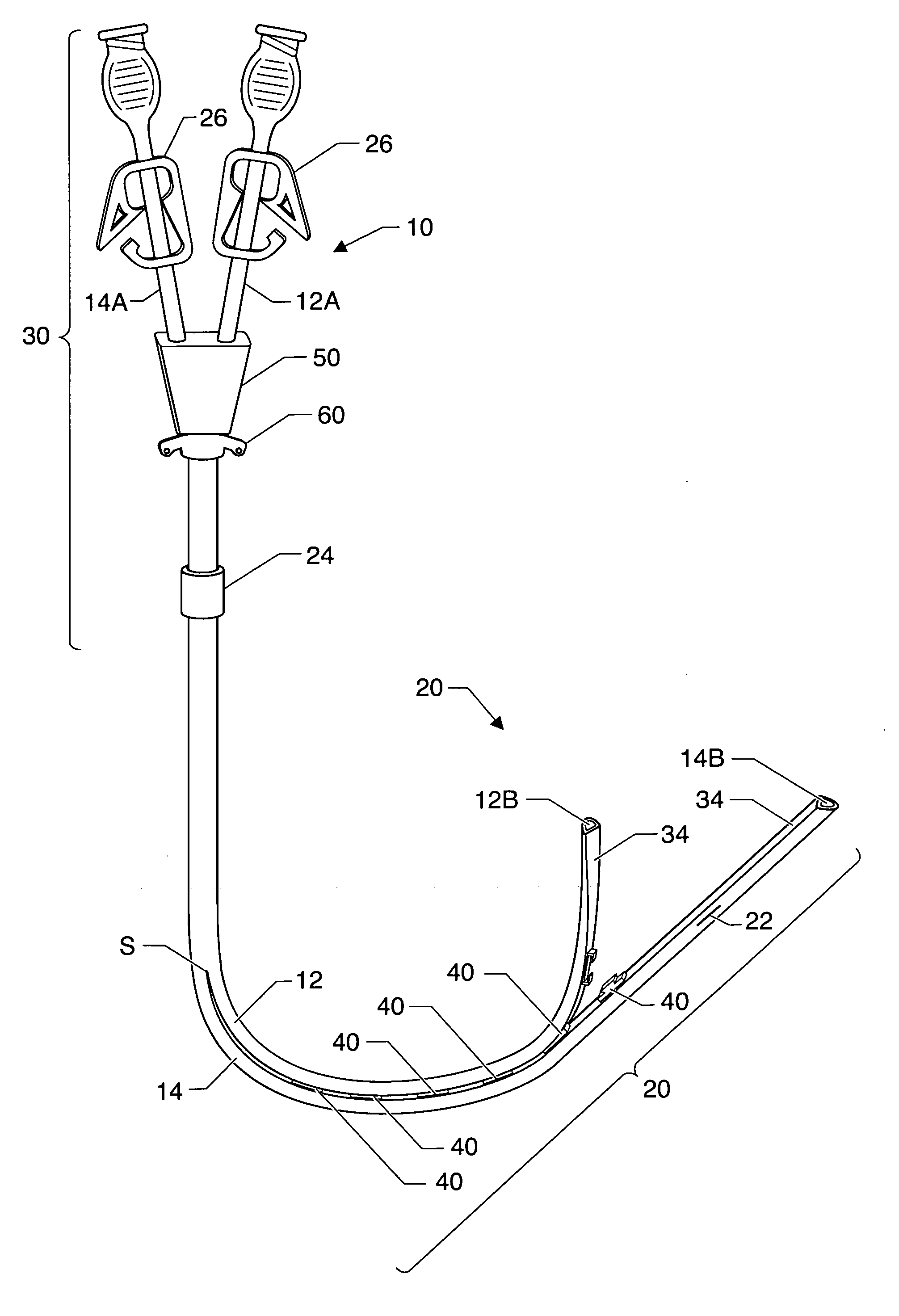
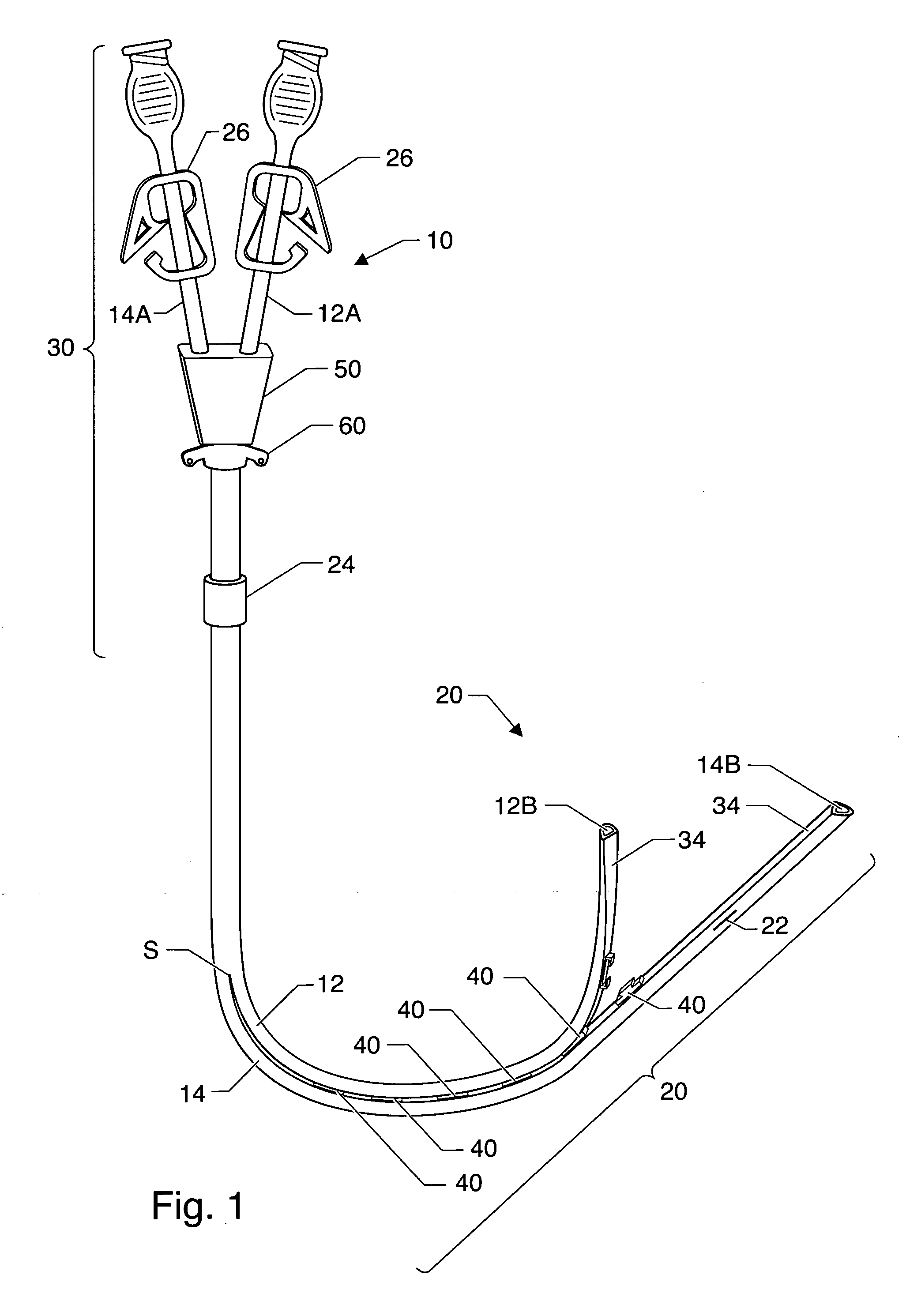
[0025] Illustrative embodiments of the present invention include multiple lumen catheter assembly 10 that has at least two joinable catheters 12, 14 such that the distance between two of the at least two catheters 12, 14 at a distal section or end 20 of the catheter assembly 10 can be varied. While the invention is described herein in conjunction with the preferred and illustrative embodiments, it will be understood that the invention is not limited to these embodiments.

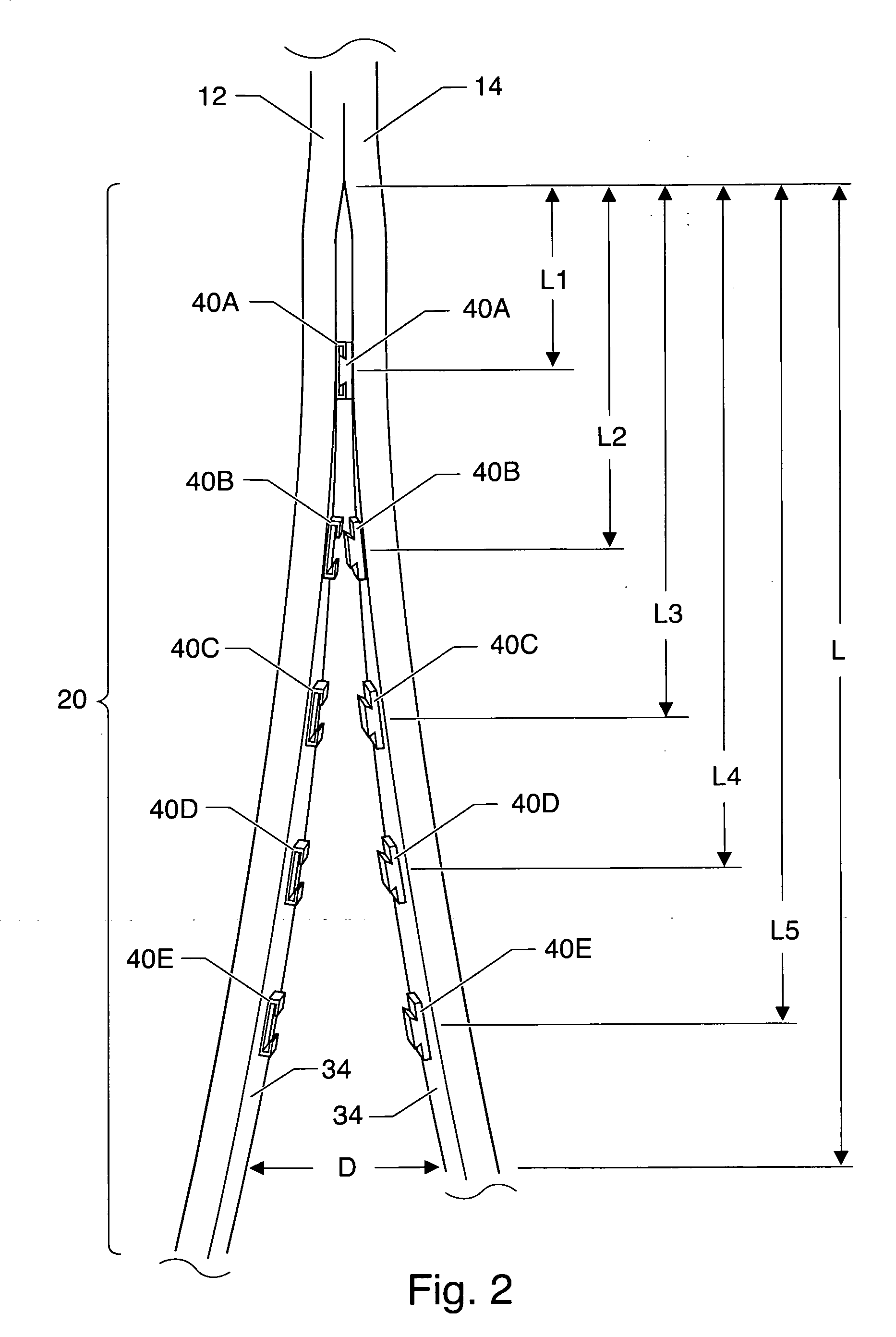
[0026] Catheter assembly 10 comprising multiple catheters 12, 14 can be constructed in accordance with the illustrative embodiments of the present invention as shown in FIGS. 1-6. FIG. 1 is a perspective view of catheter assembly 10 showing the general structure of the one illustrative embodiment in an unstressed configuration. FIG. 2 is a perspective view of a distal section 20 of the embodiment of shown in FIG. 1 showing generally the joinable catheters configuration. FIG. 3 is a perspective view of a distal secti...


PUM


Abstract

A multiple lumen catheter assembly comprising a first catheter having a proximal end and a distal end, a second catheter having a proximal end and a distal end; and a connecting means for selectively joining at least a portion of the distal ends of the first and second catheters.

Description

STATEMENT OF RELATED APPLICATIONS [0001] This patent application is a continuation application of and claims priority on U.S. patent application Ser. No. 10287566 entitled “Catheter Assembly With Joinable Catheters” having a filing date of 4 Nov. 2002, currently pending. BACKGROUND OF THE INVENTION [0002] 1. Technical Field [0003] The present invention relates generally to the field of catheters for use in applications that require blood, fluids, medicated solutions, and other solutions to be removed from and introduced into a person. More particularly, the present invention relates to catheters having dual or multiple independent catheters in which a practitioner can control the distance of separation between the lumens at the distal end of the catheters. [0004] 2. Prior Art [0005] Hemodialysis, one procedure that requires the introduction and removal of blood from a patient, is a routine treatment for patients with renal failure. When patients are placed on hemodialysis, such pati...

Claims


Application Information

Patent Timeline
Patent Type & Authority Applications(United States)
IPC IPC(8): A61M25/00
CPCA61M25/0029A61M2025/0037A61M2025/0031A61M25/0043
Inventor CUNNINGHAM, JON
Owner CUNNINGHAM JON
Why Eureka
Try Eureka