Method and apparatus for fluid dispersion

a technology of fluid dispersion and method, applied in the field of flowfocusing type technology, can solve the problems of inability to control very small dispersed phase droplets, prone to failure, and inability to precisely and accurately control small dispersed droplets in traditional industrial processes

Active Publication Date: 2005-08-11
THE GOVERNINIG COUNCIL OF THE UNIV OF TORANTO +1
View PDF97 Cites 513 Cited by
  • Summary
  • Abstract
  • Description
  • Claims
  • Application Information

AI Technical Summary

Benefits of technology

[0032] Other advantages, features, and uses of the invention will become apparent from the following detailed description of non-limiting embodiments of the invention when considered in conjunction with the accompanying drawings, which are schematic and which are not intended to be drawn to scale. In the figures, each identical or nearly identical component that is illustrated in various figures typically is represented

Problems solved by technology

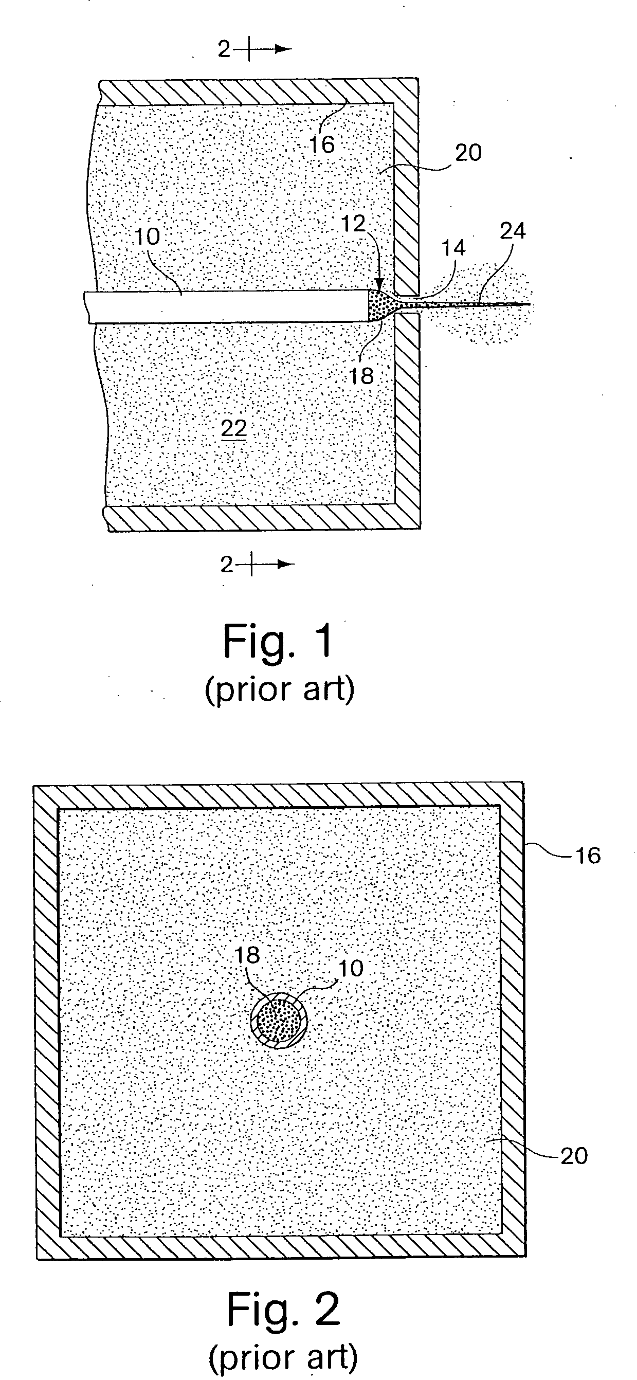
Formation of dispersions typically is carried out in equipment including moving parts (e.g., a blender or device similarly designed to break up material), which can be prone to failure and, in many cases, is not suitable for control of very small dispersed phase droplets.
Specifically, traditional industrial processes typically invol

Method used


Image

  • Method and apparatus for fluid dispersion
  • Method and apparatus for fluid dispersion
  • Method and apparatus for fluid dispersion

Examples


examples

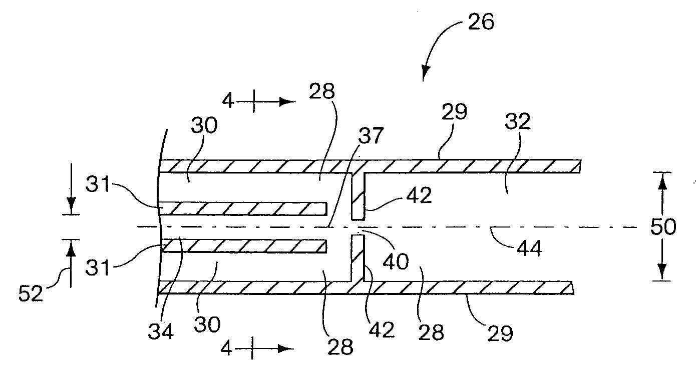
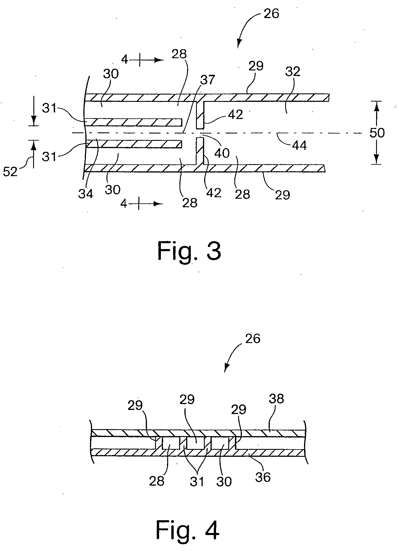
[0097] The following examples demonstrate the use of microfluidic channel geometry to form drops of a subject fluid in a continuous phase of a second, immiscible dispersing fluid. For the experiments described here, a flow-focusing-like geometry has been fabricated in a planar microchannel design using soft lithography fabrication methods; i.e. the example demonstrates the ability to rapidly produce an integrated microchannel prototype in essentially a single step. The first group of examples used oil and water as two immiscible fluids. Using oil as the continuous phase liquid (dispersing fluid) and water as the dispersed phase (subject fluid), a wide range of drop formation patterns (discontinuous sections) was realized, depending on the flow rates applied to each liquid inlet stream. Variation in size of the resulting discontinuous sections as a function of the oil flow rate, Qoil, and the ratio of the oil flow rate to the water flow rate, R=Qoil / Qwater was determined. The droplet...


PUM

PropertyMeasurementUnit
Lengthaaaaaaaaaa

Abstract

A microfluidic method and device for focusing and/or forming discontinuous sections of similar or dissimilar size in a fluid is provided. The device can be fabricated simply from readily-available, inexpensive material using simple techniques.

Description

RELATED APPLICATIONS [0001] This application is a continuation of PCT / US03 / 20542, filed Jun. 30, 2003, which was published in English and designates the United States and which claims the benefit under Title 35, U.S.C. §119(e) of U.S. provisional application No. 60 / 392,195, filed Jun. 28, 2002, and of U.S. provisional application No. 60 / 424,042, filed Nov. 5, 2002. Each of these documents is incorporated herein by reference.FIELD OF THE INVENTION [0002] The present invention relates generally to flow-focusing-type technology, and also to microfluidics, and more particularly the invention relates to microfluidic systems arranged to control a dispersed phase within a dispersant, and the size, and size distribution, of a dispersed phase in a multi-phase fluid system. BACKGROUND OF THE INVENTION [0003] The manipulation of fluids to form fluid streams of desired configuration, discontinuous fluid streams, particles, dispersions, etc., for purposes of fluid delivery, product manufacture, ...

Claims


Application Information

Patent Timeline
IPC IPC(8): B01F25/46B01L3/00B05B7/04
CPCB01F3/0807B01F5/0682B01F5/0688B01F13/0062B01F2215/0431B01F2215/045Y10T29/49002B05B7/0408B05B7/0416B05B7/0441Y10S516/924Y10S516/927Y10T436/2575B01L3/5027Y10T137/0324Y10T137/87346Y10T137/0329Y10T137/206B01F23/41B01F25/45B01F25/4521B01F33/3011
Inventor STONE, HOWARD A.ANNA, SHELLEY L.BONTOUX, NATHALIELINK, DARREN R.WEITZ, DAVID A.GITLIN, IRINAKUMACHEVA, EUGENIAGARSTECKI, PIOTRDILUZIO, WILLOWWHITESIDES, GEORGE M.
Owner THE GOVERNINIG COUNCIL OF THE UNIV OF TORANTO
Why Eureka
Try Eureka