Vertical rotary multi-functional trimming apparatus

a multi-functional, vertical rotating technology, applied in the direction of shearing apparatus, metal working apparatus, metal-working apparatus, etc., can solve the problems of easy paper pile up (or jamming), dangerous and inconvenient for users inconvenient to change the blade, etc., to achieve different trimming functions

Active Publication Date: 2005-08-11
PRIMAX ELECTRONICS LTD
View PDF3 Cites 17 Cited by
  • Summary
  • Abstract
  • Description
  • Claims
  • Application Information

AI Technical Summary

Benefits of technology

[0009] It is an advantage of the present invention a plurality of different rotary trimming elements for rotating on the material and trimming the material are utilized. Different trimming functions may be switched easily in the present design. The problem of the material piling up or becoming jammed is avoided because the friction between the material and the trimming element due to the rotating of the trimming element is less than is due to the sliding of the trimming element.
[0010] These and other objectives of the present invention will no doubt become obvious to those of ordinary skill in the art after reading the following detailed description of the preferred embodiments that are illustrated in the various figures and drawings.

Problems solved by technology

In the case that paper is to be intermittently cut (or perforated) to be easily torn off by hand later or to be marked with a folding line to be easily folded by hand, another kind of trimmer will be needed for the specific requirement, which is thus cost-ineffective and space-inefficient.
However, it is dangerous and inconvenient for users to change these blades.
Besides, it is very easy for the paper to become piled up (or jammed) when the blade slides on the paper due to the friction between the blade and the paper.
This is another one of the flaws in the conventional desktop paper cutter.
Though the design of the guiding slit may help to release the piling up problem of the paper, it increases the complexity of the paper cutter.

Method used


Image

  • Vertical rotary multi-functional trimming apparatus
  • Vertical rotary multi-functional trimming apparatus
  • Vertical rotary multi-functional trimming apparatus

Examples


first embodiment

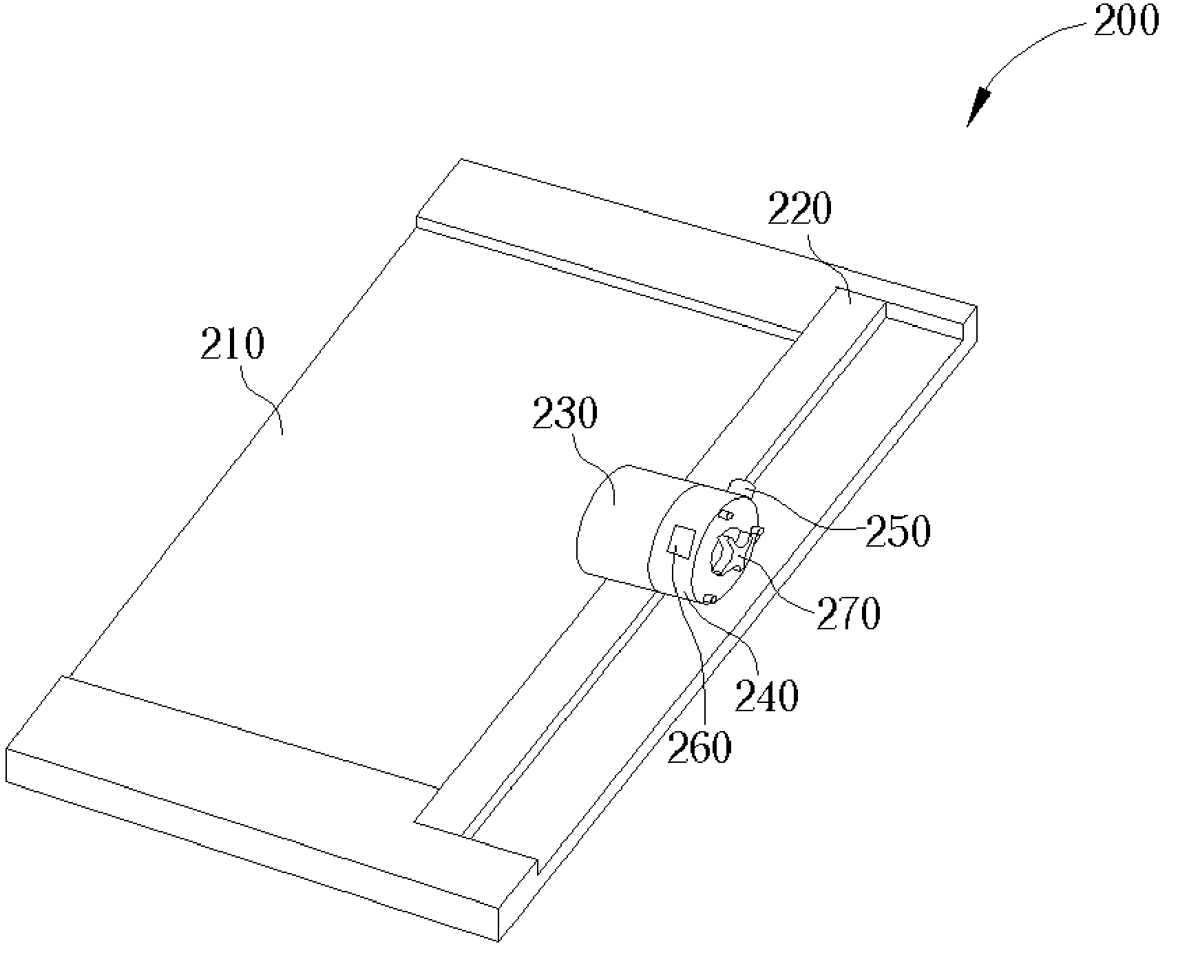
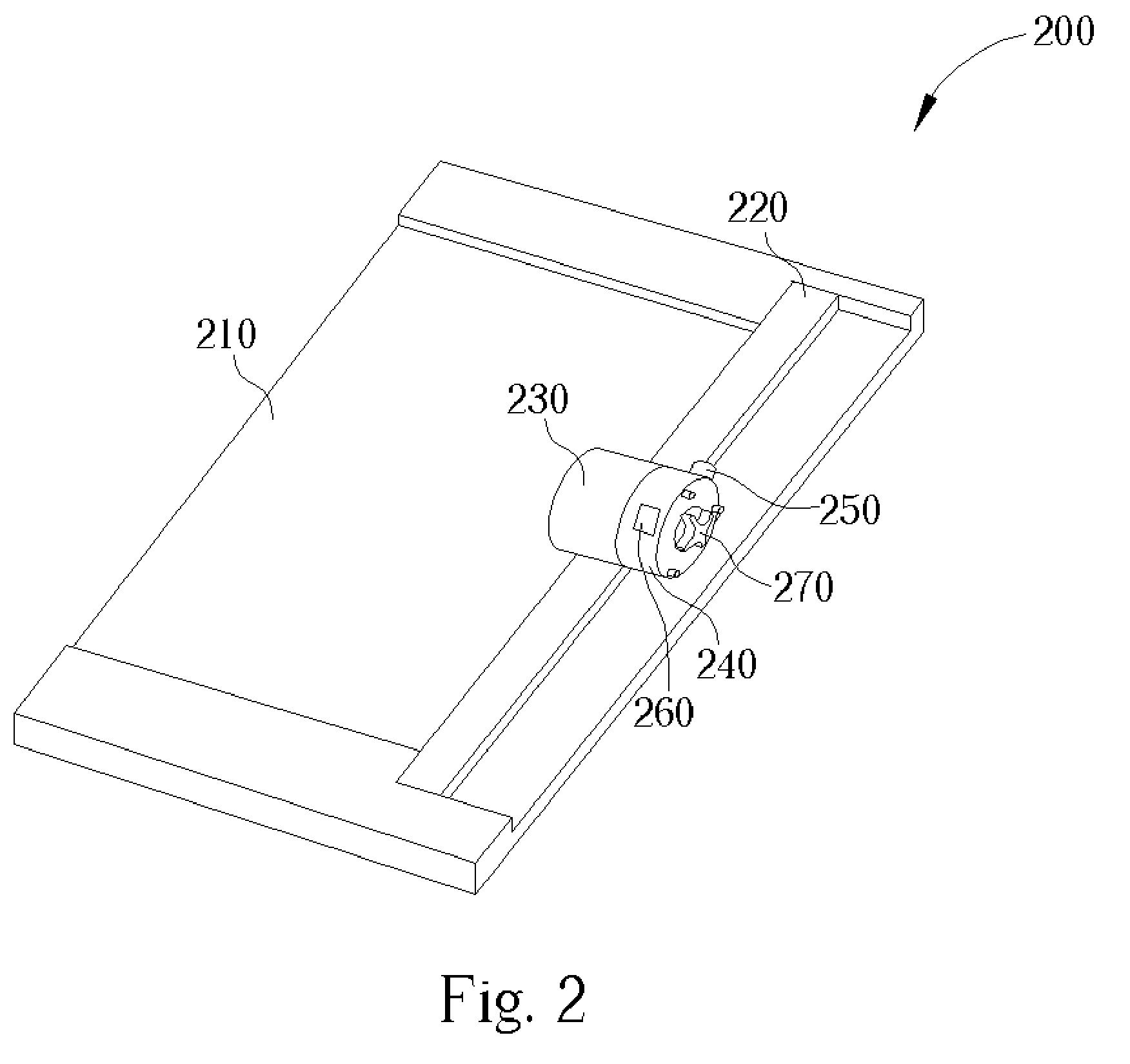
[0026] Please refer to FIG. 2. FIG. 2 is a diagram of the present invention trimming apparatus. FIG. 2 illustrates a trimming apparatus 200 comprising a base 210, a rail 220, a carriage 230 slidably mounted on the rail 220, an engagement device 270, a fixer 250, and a cover 240. The present invention is a multi-functional trimming apparatus including a plurality of different trimming elements, wherein the trimming elements are rotatably connected to the engagement device 270. The carriage 230 includes an observation window 260 for observing an indication on the engagement device 270 to allow indication of which trimming element is utilized by the trimming apparatus 200. Please refer to FIG. 3. FIG. 3 is a partial diagram of the trimming apparatus 200. In FIG. 3, the carriage 230, the engagement device 270, the fixer 250 and the plurality of trimming elements 281, 282, 283 and 284 are shown but the cover 240 in FIG. 2 is removed. The fixer 250 comprises a first unit 252 and a second ...

second embodiment

[0031] There is a spring between the engagement device 1370 and the carriage 1330 in the present invention. When a different trimming element is needed for a different trimming function, the user may press the engagement device 1370 against the carriage 1330 so the engagement device 1370 leaves the fixer 1340 and the engagement units are disengaged from the fixing units. Therefore the position of the engagement device 1370 is not fixed, and the user may hold the cross-shaped holder of the engagement device 1370 extending out the engagement device 1370 for changing the trimming element. For instance, assume that the engagements units 1371, 1372, 1373 and 1374 are engaged with the fixing units 1342, 1343, 1344 and 1341 respectively, and the trimming element 1381 is exposed so that the trimming element 1381 may rotate on the material and trim the material as the carriage 1330 slides along the rail. When the engagement device 1370 is pressed down and is rotated clockwise, and the engage...


PUM

PropertyMeasurementUnit
perimeteraaaaaaaaaa
frictionaaaaaaaaaa

Abstract

A vertical rotary trimming apparatus includes a base for placing material, a rail mounted on the base, a plurality of trimming elements for trimming the material, a carriage slidably mounted on the rail, an engagement device including a plurality of engagement units, and a fixer for engaging with the engagement units of the engagement device in order to fix the positions of the engagement device and the plurality of trimming elements. The plurality of trimming elements are rotatably connected to the engagement device, and the engagement device can actuate the plurality of trimming elements by rotating on a plane perpendicular to the base.

Description

BACKGROUND OF INVENTION [0001] 1. Field of the Invention [0002] The present invention relates to a trimming apparatus, and more particularly, to a vertical rotary multi-functional trimming apparatus. [0003] 2. Description of the Prior Art [0004] As is well known, a paper cutter is a trimming apparatus for efficiently cutting paper into small sheets. Please refer to FIG. 1. FIG. 1 is a diagram of a prior art paper cutter. The conventional paper cutter 10 includes a base 11, a rail 12, a carriage 13 and a trimming element. The base 11 is for placing the material to be trimmed, the rail 12 is fixed on the base 11, and the carriage 13 is slidably mounted on the rail 12. The trimming element is mounted on the carriage 13 and is a single specific trimming element, such as a razor blade, that is comprised in the conventional paper cutter 10. When the paper is put into a gap between the rail 12 and the base 11, the user may press down the carriage 13 against the paper. By sliding the carria...

Claims


Application Information

Patent Timeline
Patent Type & Authority Applications(United States)
IPC IPC(8): B26D1/20B26D7/26
CPCB26D1/205B26D2007/0087B26D7/2635Y10T83/7763Y10T83/8822Y10T83/8828Y10T83/9464B26B25/00B26D1/185
Inventor TSENG, TZU-FENG
Owner PRIMAX ELECTRONICS LTD
Why Eureka
Try Eureka