Magnetron

a technology of magnets and filaments, applied in the field of magnets, can solve the problems of reducing the mechanical strength of vibration or shock while carrying, affecting the performance of oscillation, and affecting the performance of oscillation, and achieves the effects of high precision, stable production, and managing the final resistance value of the filamen

Inactive Publication Date: 2005-08-11
PANASONIC CORP
View PDF12 Cites 2 Cited by
  • Summary
  • Abstract
  • Description
  • Claims
  • Application Information

AI Technical Summary

Benefits of technology

[0015] The present invention has been made to solve the above-mentioned problems, and it is an object of the present invention to provide a magnetron which prevent a variation in total amount of a carbonized layer formed in a filament from occurring and which has stable quality of a reduced variation in electric characteristic or mechanical strength of the filament and a small variation of a life span of the filament.
[0016] Further, it is another object of the present invention to provide a magnetron which can be formed without changing the electrical characteristics of the filament, thereby to secure compatibility with a power supply and so on.
[0020] For this reason, the filament having an appropriate amount of carbonized layer equipped therein can be stably produced without causing the variation in the total amount of the carbonized layer of the filament. Furthermore, the resistance value required in calculating the carbonization rate can be continuously detected and monitored by connecting a suitable detection circuit to a filament base material during a carbonization process that electrifies the filament base material to form the carbonized layer. Therefore, the formation of the carbonized layer can be managed with high precision.
[0021] Further, by managing the final resistance value of the filament and by maintaining electric strength or mechanical strength required for the filament to the same extent as that in the conventional product, the compatibility with the power supply and so on of the magnetron can be secured. In addition, the magnetron having a life span elongated about twice can be stably produced.

Problems solved by technology

However, in this case, a mechanical strength to vibration or shock while carrying is reduced due to a decrease in diameter of the core wire 6, which result in causing a disconnection of the filament or the like.
Further, there is a problem in that oscillation performance may be degraded due to degradation of the electrical characteristics.
As a result, there is a problem in that a variation in electrical characteristic or mechanical strength easily occurs at the time of serving as the filament 5.
Furthermore, there is a problem in that a significant variation in life span also occurs at the time of serving as the magnetron.
In addition, when the electrical characteristics of the filament 5 are different from those of the conventional product, there is also a problem in that compatibility as the magnetron is not implemented.

Method used


Image

  • Magnetron
  • Magnetron
  • Magnetron

Examples


Embodiment Construction

[0029] Hereinafter, a preferred embodiment of the present invention will be described in detail with reference to the drawings.

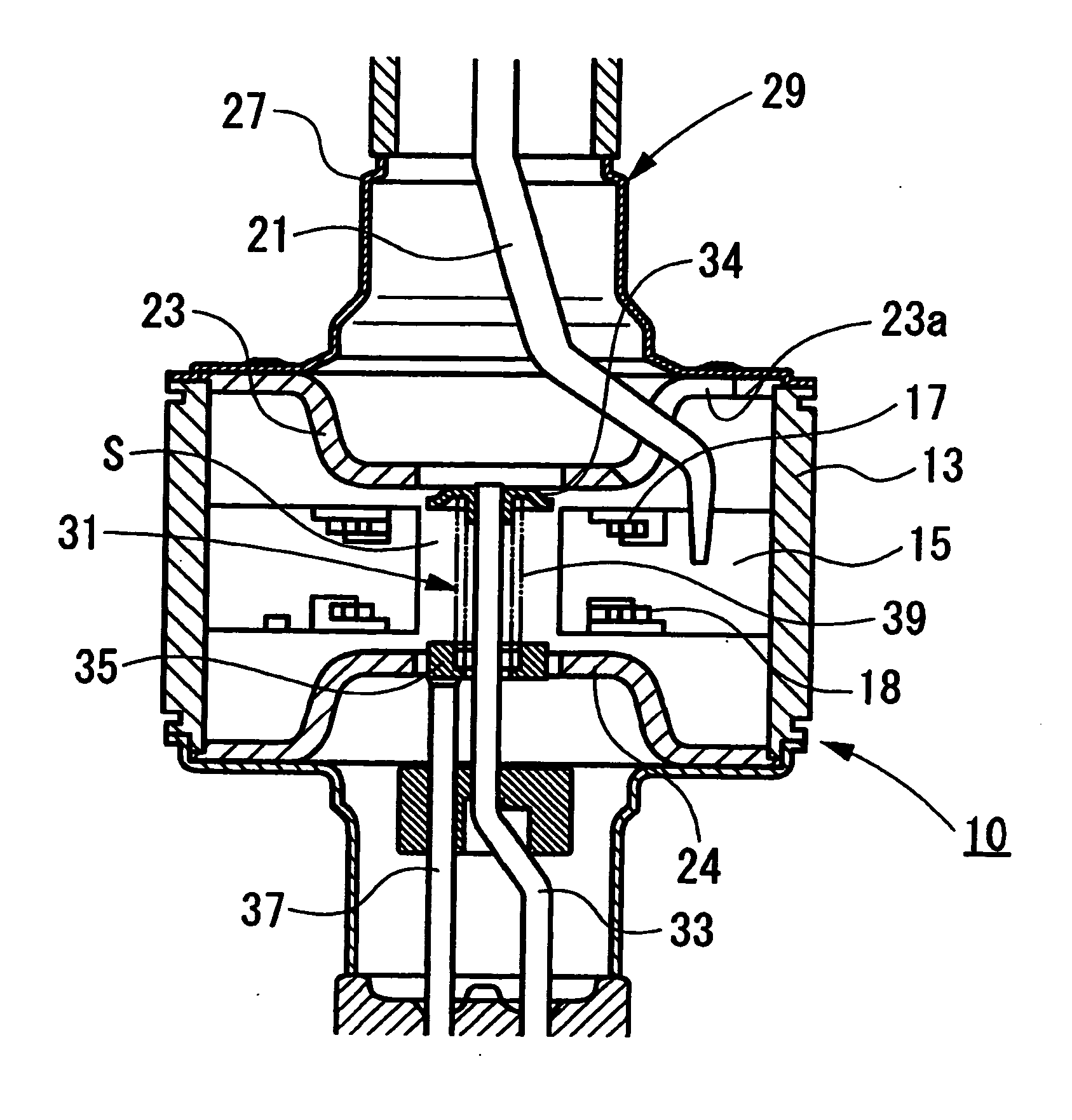
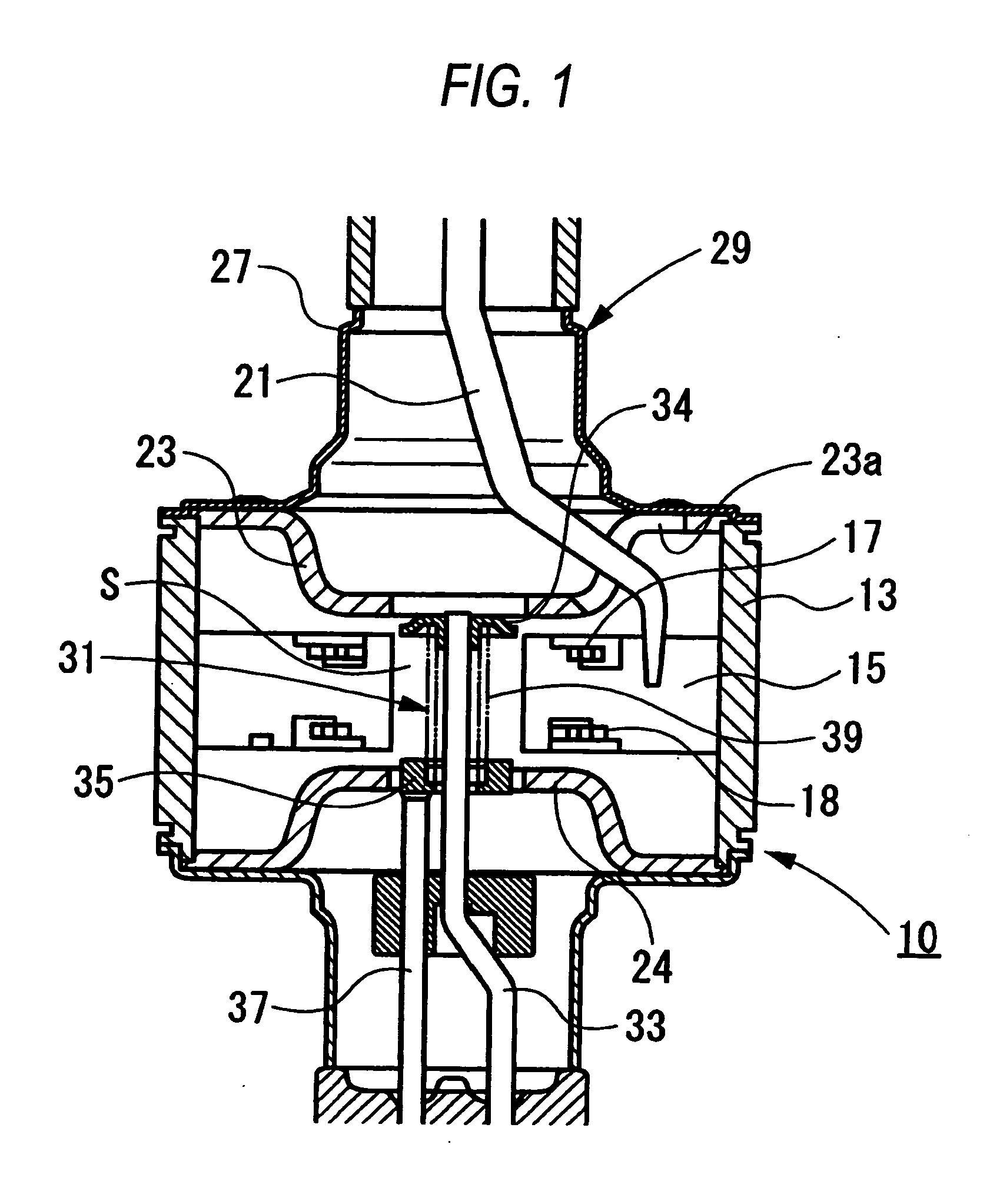
[0030]FIG. 1 shows a magnetron according to an embodiment of the present invention.

[0031] A magnetron 10 according to the embodiment of the present invention forms a cavity resonator in which even vanes 15 are fixedly arranged on an inner circumferential surface of an anode cylindrical body 13 radially toward on a central axis.

[0032] Each of the even vanes 15 has upper and lower end parts which are connected every other one by means of first and second strap links 17 and 18 in pairs. Therefore, an antenna lead 21 is connected to one vane 15 therein.

[0033] At both opening end parts of the anode cylindrical body 13, magnetic poles 23 and 24 are provided. The antenna lead 21 has a base end which is connected to an output sideline part (a sideline part near the magnetic pole 23) of the vain 15 and a front end which extends to pass through the magnetic pole 2...


PUM


Abstract

A magnetron 10 is equipped with a helical filament 39, as an element of a cathode assembly, arranged on a central axis of an anode cylindrical body 13. Assuming that a resistance value of the filament 39 before forming the carbonized layer is R1 and a resistance value of the filament 39 after forming the carbonized layer is R2, a thickness of the carbonized layer 42 of the filament 39 is determined such that a carbonization rate Rx defined by the equation “Rx={(R2−R1) / R1}×100” in a range of from 30 to 50%.

Description

BACKGROUND OF THE INVENTION [0001] The present invention relates to a magnetron for use in microwave ovens and so on, and more specifically, it relates to a magnetron having a filament improved to implement a long lifetime. [0002] Generally, a magnetron generates microwaves efficiently and is widely used in application apparatuses, particularly, such as microwave ovens and thawing apparatuses, strongly requiring stability, high quality, long lifetime, and high efficiency. [0003]FIG. 6A shows a cathode assembly of a conventional magnetron which is mounted on home electronic ovens. The cathode assembly is arranged on a central axis of an anode cylindrical body (not shown). The cathode assembly comprises a rod-shaped center lead pin 1 made of a high melting point metal, a top hat 2, made of a high melting point metal, connected to an upper end of the center lead pin 1 and an end hat 3, made of a high melting point metal, connected to a lower end of the center lead pin 1, side lead pins...

Claims


Application Information

Patent Timeline
Patent Type & Authority Applications(United States)
IPC IPC(8): H01J9/04H01J23/04H01J23/05H01J25/50
CPCH01J9/04H01J25/587H01J23/05
Inventor INAMI, MASAHIRO
Owner PANASONIC CORP
Why Eureka
Try Eureka