
Opening device for can

a technology for opening devices and cans, which is applied in the field of beverage can opening devices, can solve the problems of difficulty in substantially simultaneously opening the two opening portions, natural inconvenience of use, and limitations on the design of cans in view of strength, and achieves the effect of convenient opening

Inactive Publication Date: 2005-08-11
HWANG BO YEOUN
View PDF23 Cites 16 Cited by
  • Summary
  • Abstract
  • Description
  • Claims
  • Application Information

AI Technical Summary

Benefits of technology

[0016] An object of the present invention is to provide an opening device for a can constructed such that contents of the can are able to flow out very smoothly to the outside.
[0019] According to the present invention, the second opening portion is opened while being lifted together with the tab, and the first opening portion is opened while being pressed downward. Therefore, it is expected to obtain an advantage in that the pair of opening portions may be more easily opened as a whole.

Problems solved by technology

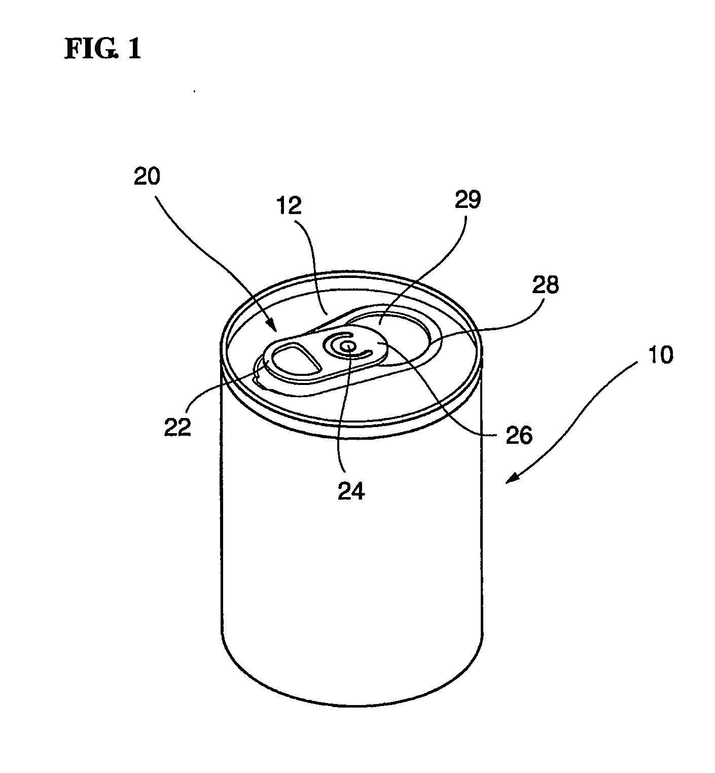
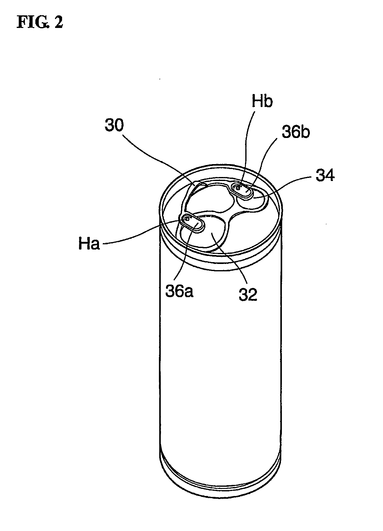
However, according to the conventional opening device shown in the figure, it is not easy to substantially simultaneously open the two opening portions.
That is, since the grip should be pulled up with a force larger than that required for a conventional opening device for opening a single opening portion, there is naturally inconvenience of use.
Further, since sufficient strength resistant to such a larger force should be ensured between the grip and the pressing portions, there is a disadvantage in that there are limitations on the design thereof in view of strength.

Method used


Image

  • Opening device for can
  • Opening device for can
  • Opening device for can

Examples


Embodiment Construction

[0026] Hereinafter, the present invention will be described in detail in connection with preferred embodiments illustrated in the accompanying drawings.

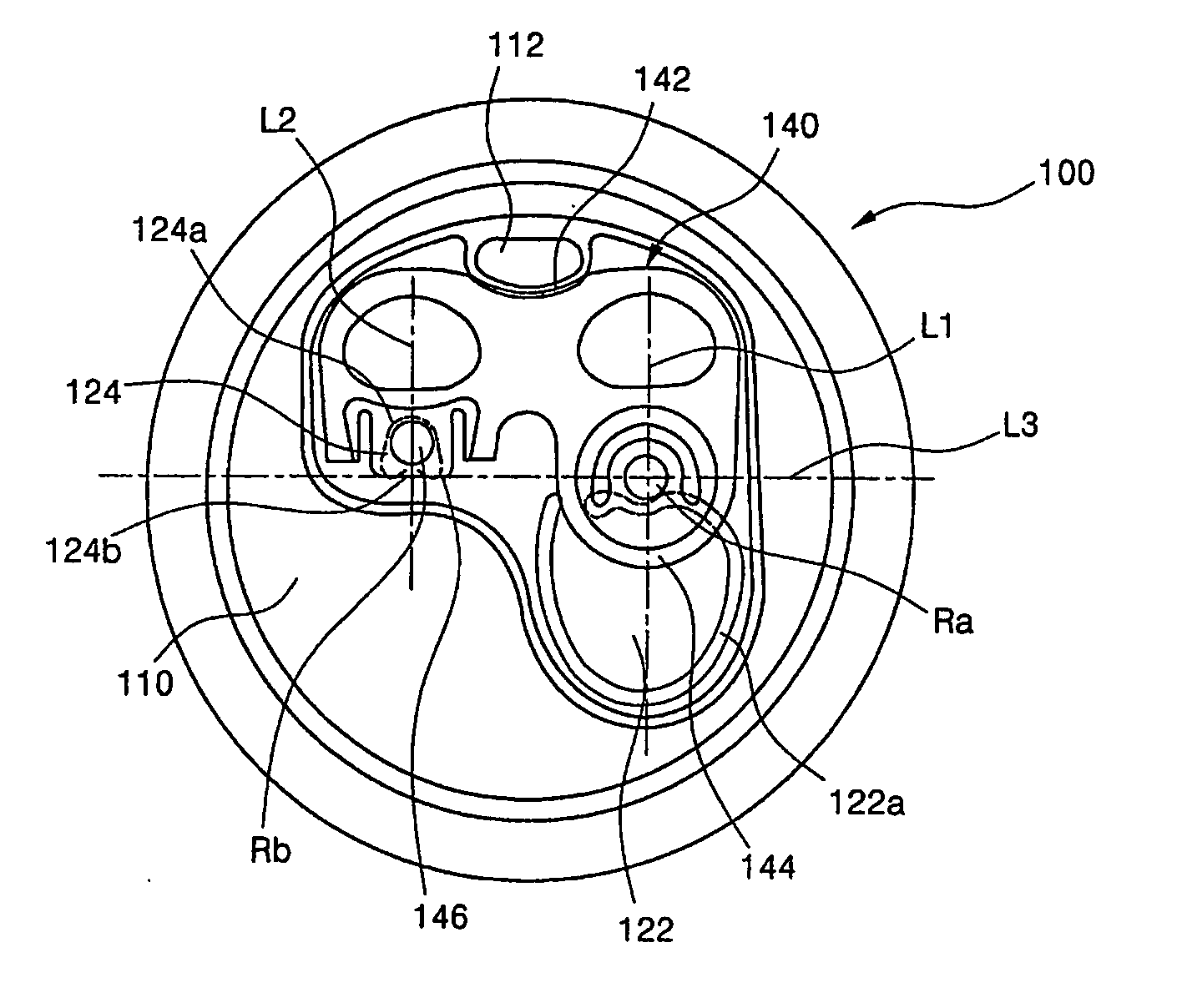
[0027]FIG. 3 shows a plan view of a can with an opening device according to a first embodiment of the present invention.

[0028] As shown in the figure, the opening device of the present invention includes a pair of opening portions 122 and 124 formed on a top surface 110 of the can 100. The opening portions 122 and 124 include a first opening portion 122 through which the contents of the can flow out upon opening thereof, and a second opening portion 124 through which exterior air is introduced into the can upon opening thereof while the contents of the can flows out through the second opening portion 122. As shown in the figure, the first opening portion 122 is formed to be relatively larger than the second opening portion 124. Further, the first and second opening portions 122 and 124 are formed at symmetrical positions of the top...


PUM


Abstract

The present invention relates to an opening device for a can, which is constructed such that the contents of the can flow out and exterior air is simultaneously introduced into the can. The opening device of the present invention comprises first and second opening portions 122 and 124 through which the contents flow out and the exterior air is introduced into the can upon opening thereof, respectively, and which are disposed to be opposite to each other at both sides of the top surface 110 of the can and defined by incision lines 122a and 124a so that a part of each of the opening portions is attached to the top surface; and a tab 140 mounted on the top surface of the can by means of a first rivet stub Ra installed outside of the first opening portion and a second rivet stub Rb installed within the second opening portion. The second opening portion is opened while being lifted together with the second rivet stub Rb, the first opening portion is opened while being pressed by a pressing portion 144 around the first rivet stub, and the second rivet stub is formed to be closer to a grip 172 of the tab 170 than the first rivet stub.

Description

TECHNICAL FIELD [0001] The present invention relates to an opening device for a beverage can, and more particularly, to an opening device for a can, which is constructed such that beverage contained within the can is able to flow out more easily. BACKGROUND ART [0002]FIG. 1 is a perspective view of an opening portion of a conventional can. As shown in the figure, contents such as beverage or beer to be drunk are generally contained within a can body 10, and an opening device for opening the can is generally attached to a top surface 12 or bottom surface of the can body. An opening member 20 attached to the top surface 12 through a rivet stub 24 is used to open a predetermined portion of the top surface of the can body 10. Further, the opening member 20 comprises a grip 22 extending to one side with respect to the rivet stub 24, and a pressing portion 26 extending to the opposite side with respect to the rivet stub 24. [0003] An opening portion 29 defined by an incision line 28 groov...

Claims


Application Information

Patent Timeline
Patent Type & Authority Applications(United States)
IPC IPC(8): B65D17/34
CPCB65D2517/0014B65D17/165Y10S220/906B65D17/4012B65D17/00
Inventor HWANG, BO-YEOUN
Owner HWANG BO YEOUN
Learn More