Pipe and cable support apparatus and method

a technology of supporting apparatus and pipe, which is applied in the direction of pipe supports, pipes/joints/fittings, domestic objects, etc., can solve the problems of high unit cost, large amount of man-hours, and high unit cost of certain devices used,

Inactive Publication Date: 2005-08-11
PATTERSON VENTILATION
View PDF9 Cites 46 Cited by
  • Summary
  • Abstract
  • Description
  • Claims
  • Application Information

AI Technical Summary

Benefits of technology

[0011] In one embodiment, a roof cooling system for providing a cooling effect on a roof, the system comprising a plurality of pipes, a plurality of spray heads arranged on each pipe for spraying water on the roof, a controller for controlling the spraying of water, and a plurality of support blocks for supporting the plurality of pipes above the roof, wherein each block comprises a plurality of outer surfaces, each outer surface having at least one opening communicating with a cavity, each cavity being designed to fit a pipe of a predetermined diameter, is disclosed.

Problems solved by technology

To support or arrange these pipes, conduits, cables, and wires, certain means or devices are used which can have high unit cost, and require the use of installation tools or a large amount of man-hours to install, especially for large-scale projects.
The pipes, however, are exposed to the environment, including the ambient temperature and solar radiation, and therefore undergo thermal expansion and contraction.
If the pipes are fixed onto the supporting structures and the supporting structures are themselves fixed onto the roof, the expansion and contraction of the pipes can impart stress and potentially damage the supporting structures or the roof surface or both.
For a roof cooling system with a number of pipe runs and requiring a large number of supporting structures, the total amount of time and labor required to install the individual supporting structures in a roof cooling system, for example, becomes prohibitively expensive.
Similarly, the installation of pipes, conduits, cables, or wires could also incur high cost.

Method used


Image

  • Pipe and cable support apparatus and method
  • Pipe and cable support apparatus and method
  • Pipe and cable support apparatus and method

Examples


Embodiment Construction

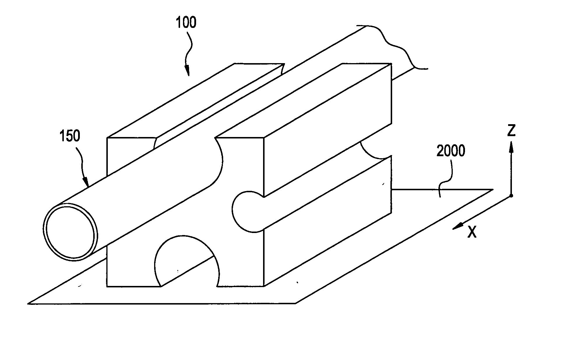
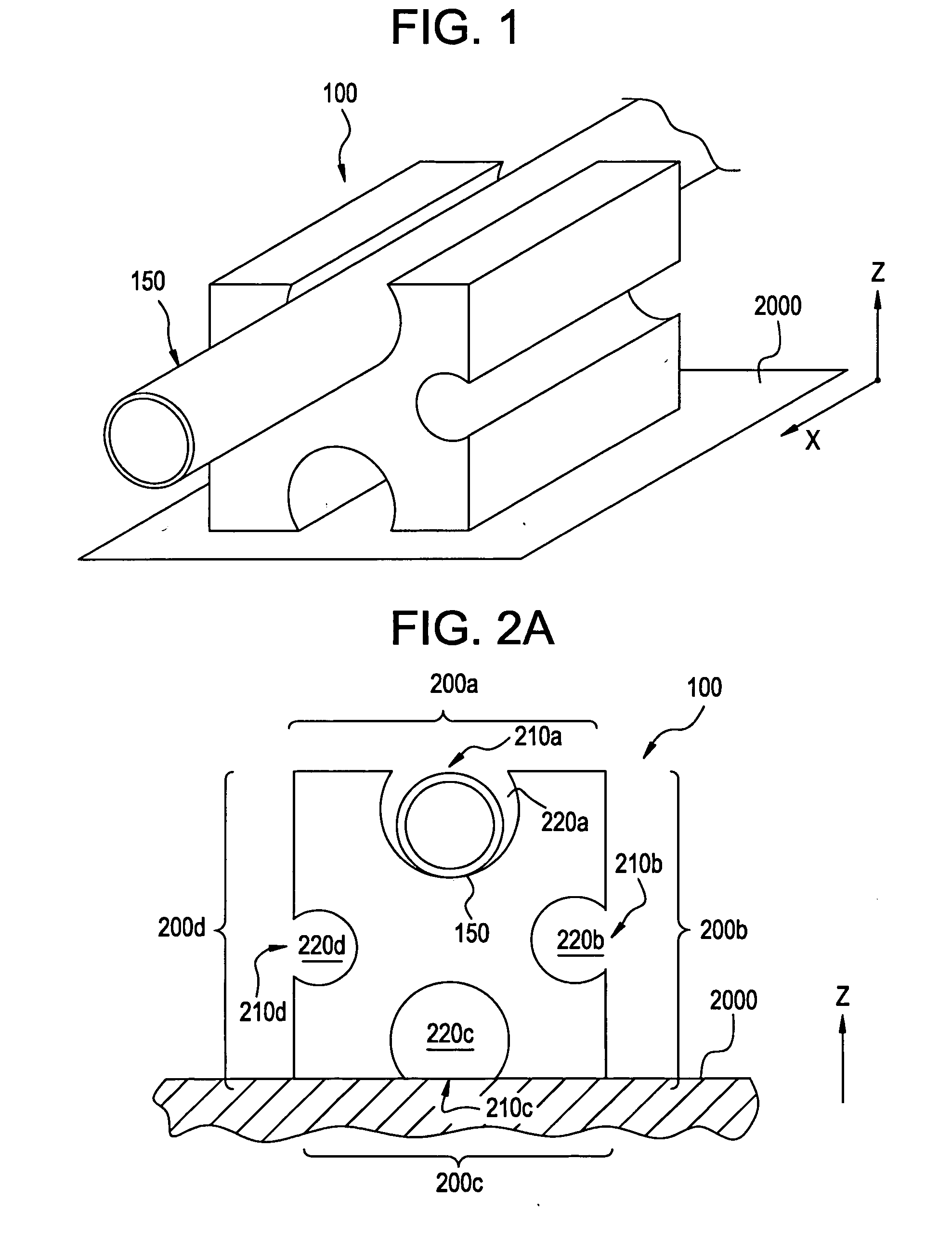
[0026] An exemplary embodiment will now be described with reference to FIGS. 1, 2A, and 2B. A perspective view of a support block 100 is shown in FIG. 1, and a cross sectional view of the same is shown in FIG. 2A. The support block 100 rests on the surface of a structure such as a roof, ceiling tiles, structural frame, or the like. Alternatively, in another embodiment, the support block is disposed or suspended below such structures. The support block 100 can support at least one of pipes, conduits, cables, wires, and the like. In FIG. 2A, the support block rests on the surface of a roof 2000 and a pipe 150 fitted in the support block 100. The following embodiment describes the support block 100 as used in an exemplary application.

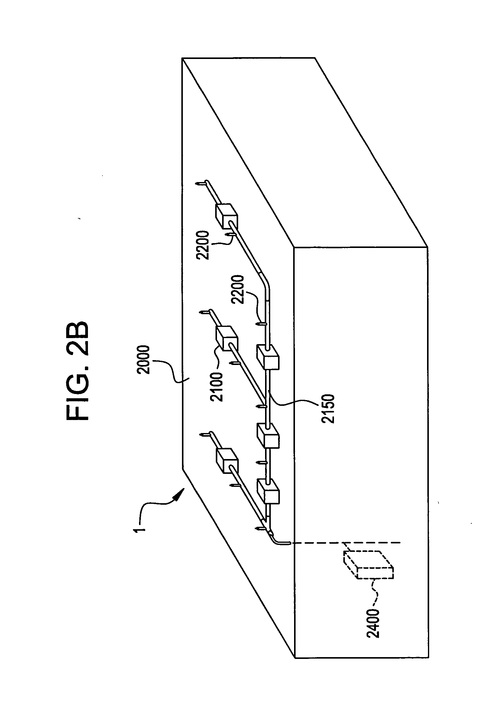
[0027] As shown in FIG. 2B, the pipe 150 is one of a plurality of pipes 2150 of a roof deck cooling system 1. The roof deck cooling system 1 utilizes water distributed to and applied on the surface of the roof 2000 through spray nozzles 2200. The spray no...


PUM


Abstract

The present invention relates to a support block and a system for roof cooling. The support block supports a pipe above a structure, wherein the pipe has a cross sectional area and a diameter of predetermined dimensions, and the support block includes a number of outer surfaces each having an opening and a cavity. Each cavity has a cross sectional area larger than the cross sectional area of a pipe and the opening can be less than the diameter of the cavity cross sectional area or slightly less than the diameter of a pipe. Dovetail notches on the surfaces of the support block are present to attach the support block onto the roof. Adhesives can be used in the dovetail notches or an adaptor plate attached to the roof can be used to attach the support block to the adaptor plate. Alternatively, the support block can be used to assist in supporting and routing any type of conduit or cabling.

Description

BACKGROUND OF THE INVENTION [0001] 1. Field of the Invention [0002] This invention relates to a support apparatus and a support method. More particularly, the invention relates to a support block for supporting pipes and cables above or below a surface including roofs and ceilings and a method for the same. Further, the invention relates to a system for cooling roofs using conduit support blocks. [0003] 2. Description of the Related Art [0004] In commercial and residential buildings, there are numerous pipes, conduits, cables, wires, and the like, of various sizes installed on or inside the buildings. Often, there is a hodgepodge of pipes, conduits, cables, and wires run above or below ceilings, on or below roofs, or along or next to a structural or aesthetic member of the building. To support or arrange these pipes, conduits, cables, and wires, certain means or devices are used which can have high unit cost, and require the use of installation tools or a large amount of man-hours t...

Claims


Application Information

Patent Timeline
Patent Type & Authority Applications(United States)
IPC IPC(8): F16L3/22F16L3/223
CPCF16L3/22F16L3/223F16L3/222
Inventor FARRELL, MICHAEL GERENMOORE, MARK EUGENEPATTERSON, VANCE MARTINTHOMAS, DONALD JAY JR.YONCE, HENRY LEE
Owner PATTERSON VENTILATION
Why Eureka
Try Eureka