Heat-assisted hermetic spring seal

a technology of hermetic springs and seals, applied in the direction of engine seals, sealing carrier gaskets, and reducing carrier contamination, can solve the problems of insufficient sealing methods used in disc drives to provide containment of helium, the spacing or fly height between data storage discs and disc head sliders is extremely close, and requires an extremely clean environmen

Inactive Publication Date: 2005-08-11
SEAGATE TECH LLC
View PDF19 Cites 20 Cited by
  • Summary
  • Abstract
  • Description
  • Claims
  • Application Information

AI Technical Summary

Benefits of technology

[0008] The hermetic seal comprises an externally accessible surface for selectively a

Problems solved by technology

In particular, a spacing or fly height between data storage discs and disc head sliders is extremely close and requires an extremely clean environment.
It is found, however, that housing sealing methods used in disc drives are not adequate to provide containment of helium over an operating life of a disc drive, which is typically five years or more.
Disc driv

Method used


Image

  • Heat-assisted hermetic spring seal
  • Heat-assisted hermetic spring seal
  • Heat-assisted hermetic spring seal

Examples


Embodiment Construction

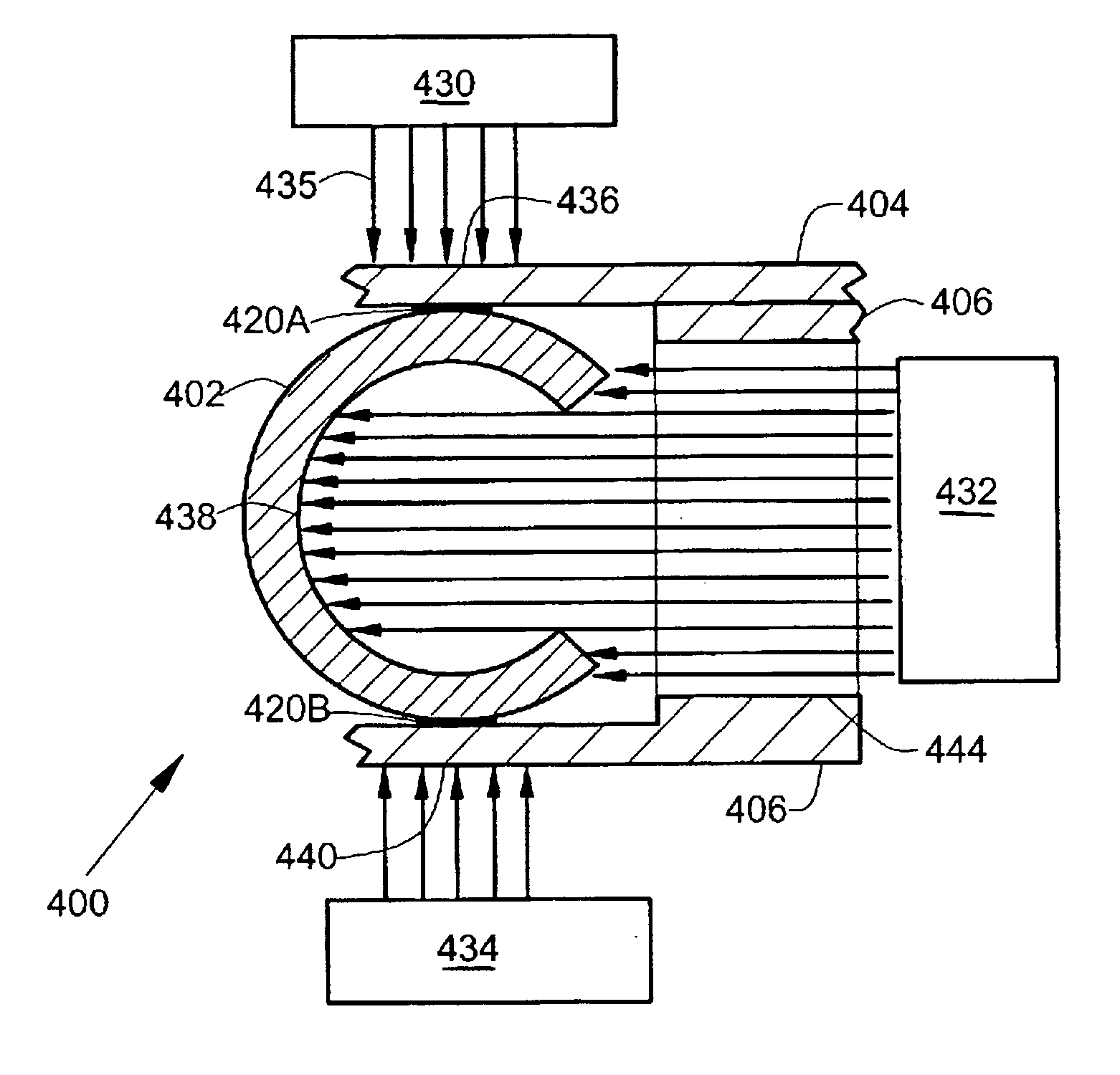
[0017] In the embodiments described below in FIGS. 1, 3-11, a hermetic seal between cover faces is provided that does not require high compression forces, can be used with non-ideal seal face finishes, and does not require heating that can damage heat sensitive components. A spring seal is compressed between the cover faces with a limited sealing force. A heat-sealable film is provided that joins the spring seal to the cover faces. Heat is selectively applied to an externally accessible surface to selectively heat the film. The film is softened by the heat and deforms to fill surface roughnesses on the cover faces and form a hermetic seal without the use of high compressive forces. The completed hermetic seal is cooled, and a fill gas such as helium is introduced into a cavity surrounded by the hermetic seal. The arrangement provides long term retention of the fill gas needed for years of operation. The arrangement allows helium filled disc drives to be manufactures economically and...


PUM


Abstract

A hermetic seal includes a spring seal compressed with a limited sealing force between sealing surfaces. The sealing surfaces surround a gas-filled cavity that houses heat sensitive components. The hermetic seal includes a film that joins the spring seal to the sealing surfaces. The film includes a material that is softenable by heat to hermetically seal the spring seal to the sealing surfaces. The hermetic seal includes an externally accessible surface for selectively application of the heat to the film, without overheating the heat sensitive components.

Description

CROSS-REFERENCE TO RELATED APPLICATION [0001] This application claims the benefit of U.S. Provisional Application 60 / 541,991, filed on Feb. 5, 2004 for inventor Neal F. Gunderson and entitled “Heat Assisted Metal Sealing Of HDA.”FIELD OF THE INVENTION [0002] The present invention relates generally to hermetic seals, and more particularly but not by limitation to hermetic seals that are maintained with a reduced compressive sealing force or non-ideal sealing surfaces. BACKGROUND OF THE INVENTION [0003] Magnetic storage devices, such as disc drives, are typically enclosed in housings to provide a clean, particle-free environment for internal components to operate with close spacings between moving parts. In particular, a spacing or fly height between data storage discs and disc head sliders is extremely close and requires an extremely clean environment. There is a desire to increase areal density of information storage on data storage discs and to make corresponding reductions in fly ...

Claims


Application Information

Patent Timeline
IPC IPC(8): F16J15/02F16J15/08G11B33/14
CPCF16J15/0806G11B33/1466F16J15/0887
Inventor GUNDERSON, NEAL FRANK
Owner SEAGATE TECH LLC
Why Eureka
Try Eureka