MEMS actuator for piston and tilt motion

a technology of actuators and pistons, applied in the field of microelectromechanical systems, can solve the problems of affecting the alignment of the interleaved structure affecting the image quality, and affecting the alignment of the comb-shaped portion,

Active Publication Date: 2005-08-11
ALCATEL-LUCENT USA INC +1
View PDF8 Cites 10 Cited by
  • Summary
  • Abstract
  • Description
  • Claims
  • Application Information

AI Technical Summary

Benefits of technology

[0009] In another embodiment, the MEMS device has a motion drive with two comb-shaped portions. Each of the comb-shaped portions is (i) attached to a corresponding flexible beam, (ii) interleaved with the other comb-shaped portion, and (iii) adapted to move with respect to the substrate and that other comb-shaped portion. When a voltage differential is applied between the comb-shaped portions, they move substantially parallel to the substrate, thereby changing the shape of the beams and translating / rotating the movable bar. Advantageously, such a motion drive can be positioned at one side of the spring structure and, yet, provide a symmetric deformation of the flexible beams.

Problems solved by technology

The cumulative effect of these changes along the beam propagation path may lead to beam wandering and spreading and to beam intensity fluctuations, each of which degrades image quality.
During the device fabrication process, the offset comb-shaped portions are typically formed in different layers of a layered wafer, which may result in certain wafer processing problems.
For example, it may be relatively difficult to achieve proper alignment of the interleaved structures of said comb-shaped portions with respect to each other because different layers are processed during different fabrication steps using different lithographic masks.

Method used


Image

  • MEMS actuator for piston and tilt motion
  • MEMS actuator for piston and tilt motion
  • MEMS actuator for piston and tilt motion

Examples


Embodiment Construction

[0019] Reference herein to “one embodiment” or “an embodiment” means that a particular feature, structure, or characteristic described in connection with the embodiment can be included in at least one embodiment of the invention. The appearances of the phrase “in one embodiment” in various places in the specification are not necessarily all referring to the same embodiment, nor are separate or alternative embodiments mutually exclusive of other embodiments.

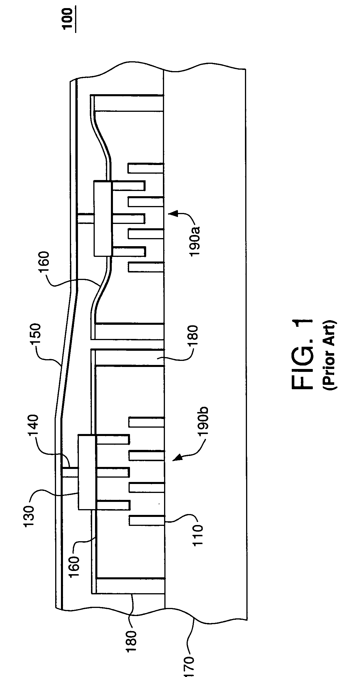
[0020]FIG. 1 shows a side view of a representative prior-art device 100 disclosed in U.S. Pat. No. 6,384,952. Device 100 has a deformable membrane 150 connected to a plurality of actuators 190 supported on a substrate 170. Only two actuators 190a-b of the plurality are shown in FIG. 1. Each actuator 190 has (i) a stator 110 attached to substrate 170 and (ii) a slider 120 supported on the substrate by two anchors 180 and a spring 160. To transfer motion of slider 120 to membrane 150, device 100 has a pole 140 attached between the ...


PUM


Abstract

A MEMS device having a spring structure formed by two flexible beams attached between a substrate and a movable bar. When non-end sections of the beams are pulled in opposite directions, the beam ends attached to the movable bar pull that bar toward the substrate, thereby transforming in-plane motion of the non-end sections into out-of-plane motion of the movable bar. When the non-end sections are displaced symmetrically, the movable bar translates toward the substrate. Alternatively, when the non-end sections are displaced non-symmetrically, the movable bar rotates with respect to the substrate. In one embodiment, each flexible beam is attached to a comb-shaped portion of a motion actuator, which has two such portions, each portion interleaved with the other portion and adapted to move with respect to the substrate and that other portion. When a voltage differential is applied between the portions, they move substantially parallel to the substrate, thereby deforming the beams and translating/rotating the movable bar.

Description

BACKGROUND OF THE INVENTION [0001] 1. Field of the Invention [0002] The present invention relates to adaptive optics and, more specifically, to micro-electromechanical systems (MEMS) for implementing adaptive optics. [0003] 2. Description of the Related Art [0004] Adaptive optics is a field of optics dedicated to the improvement of optical signals using information about signal distortions introduced by the environment in which the optical signals propagate. An excellent introductory text on the subject is given in “Principles of Adaptive Optics” by R. K. Tyson, Academic Press, San Diego, 1991, the teachings of which are incorporated herein by reference. [0005] A representative example of an adaptive optical element is a deformable mirror driven by a wavefront sensor and configured to compensate for atmospheric distortions that affect telescope images. Small naturally occurring variations in temperature (˜1° C.) in the atmosphere cause random turbulent motion of the air and give ris...

Claims


Application Information

Patent Timeline
Patent Type & Authority Applications(United States)
IPC IPC(8): G02B26/08
CPCG02B26/0841
Inventor GREYWALL, DENNIS S.
Owner ALCATEL-LUCENT USA INC
Why Eureka
Try Eureka