Laser depilator

a depilator and laser technology, applied in the field of laser depilators, can solve the problems of user discomfort in performing the above-described depilation treatmen

Inactive Publication Date: 2005-08-11
YA MAN LTD
View PDF14 Cites 151 Cited by
  • Summary
  • Abstract
  • Description
  • Claims
  • Application Information

AI Technical Summary

Benefits of technology

[0005] Laser depilatory is said that it must be performed continuously for a long period. For example, it is said that the effect can be obtained after a lapse of at least about three months after starting

Problems solved by technology

Therefore, it is troublesome for the user to perform the above-described d

Method used


Image

  • Laser depilator
  • Laser depilator
  • Laser depilator

Examples


first embodiment

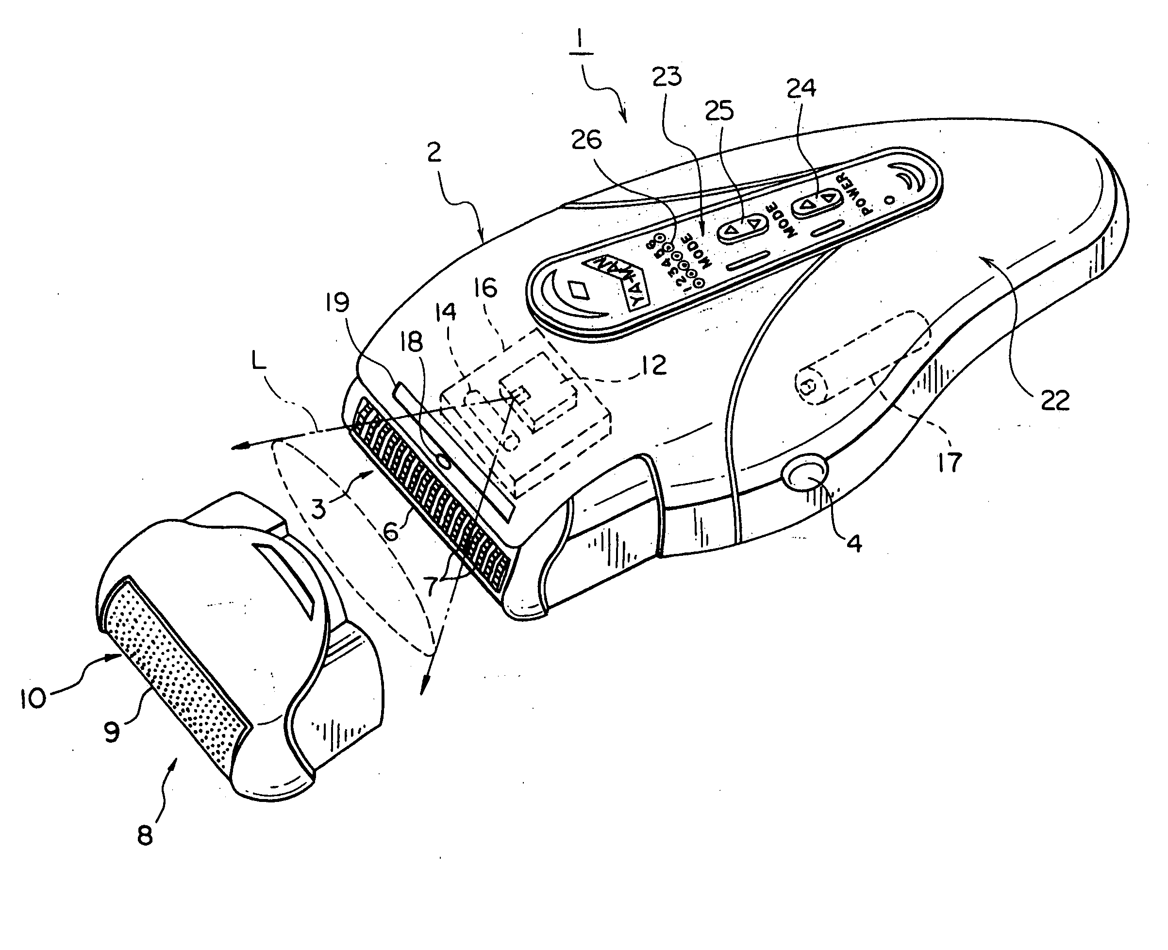
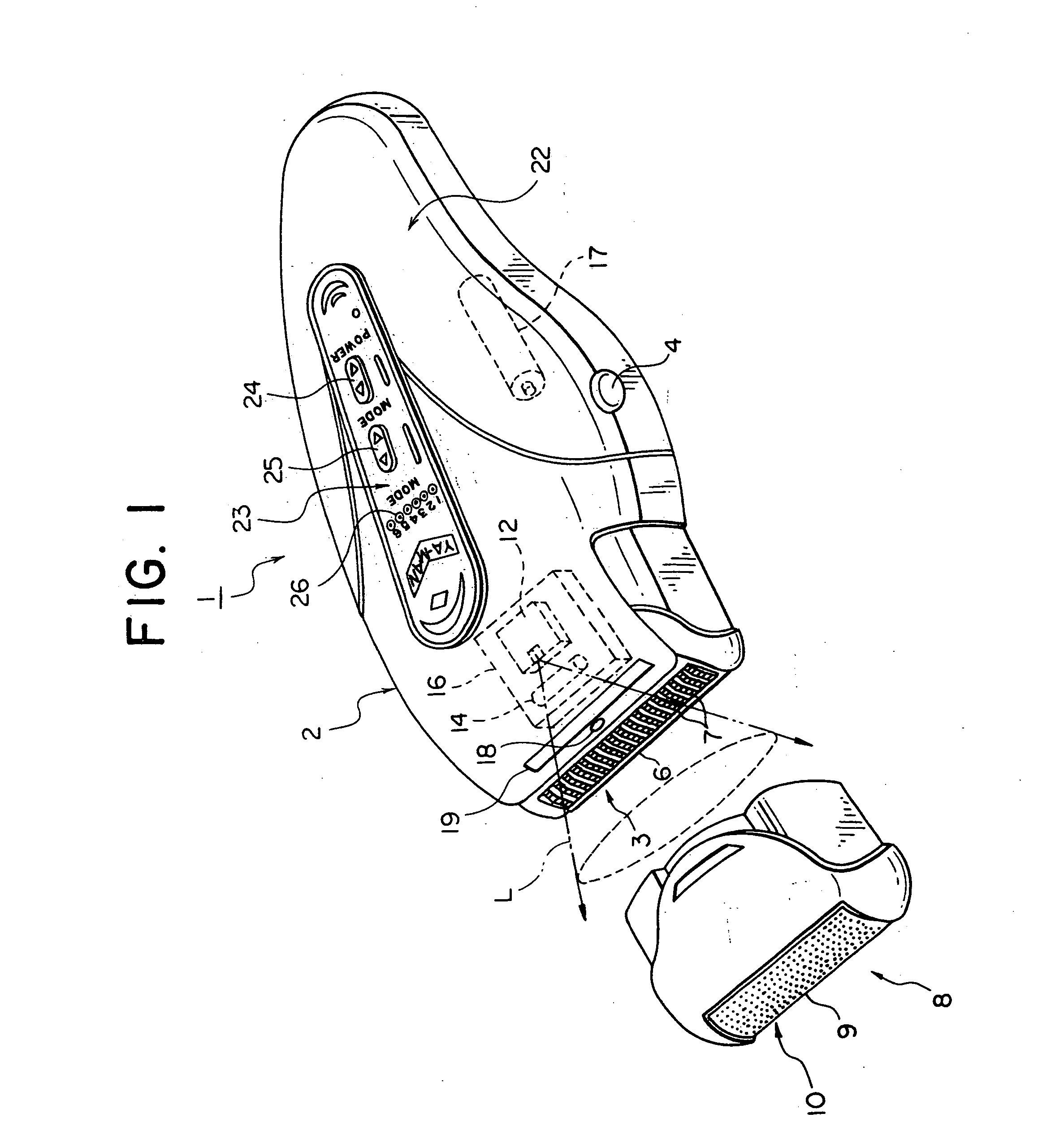
[0053]FIG. 1 is a perspective diagram showing the laser depilator according to the first embodiment of the invention.

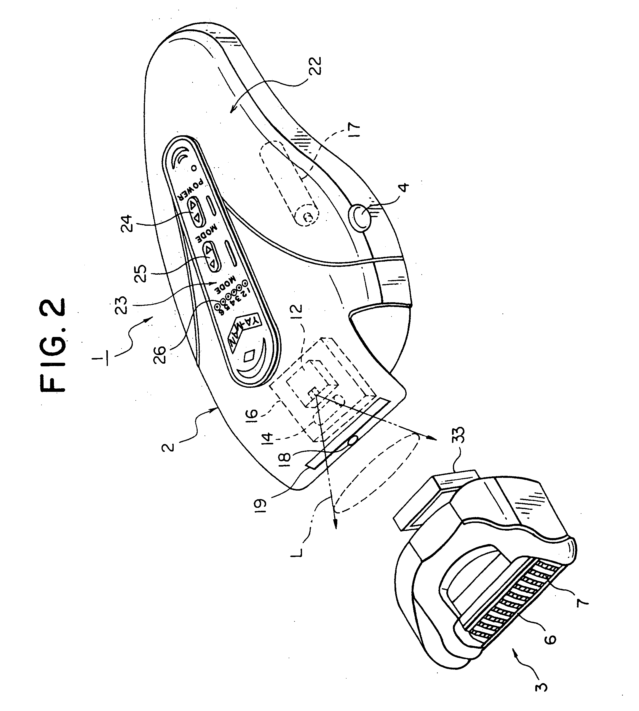
[0054]FIG. 2 is a perspective diagram showing a state of the laser depilator of FIG. 1 with a tweezer head unit removed from the laser depilator body, FIG. 3 is a perspective diagram showing a state of the laser depilator of FIG. 1 with a shaving head unit attached to the laser depilator body, and FIG. 4 is a functional block diagram showing a control system of the laser depilator of FIG. 1. FIG. 5 is a partially sectional diagram showing a state of depilating by the laser depilator of FIG. 3, and FIG. 6 is a plan diagram showing the skin surface under depilation treatment by the laser depilator of FIG. 3.

[0055] As shown in FIG. 1 to FIG. 3, this laser depilator 1 is used by a user oneself to perform a laser depilation treatment (laser depilation treatment) and comprised of a laser depilator body 2, a tweezer head unit 3 and a shaving head unit 8 which are detachabl...

second embodiment

[0097]FIG. 8 is a perspective diagram showing a laser depilator 41 according to the second embodiment of the present invention. The laser depilator 41 has a spherical lens 42 instead of the cylindrical lens 14 and also an irradiation position changing unit 43 for changing the irradiated position of laser light.

[0098] The spherical lens 42 functions as a condenser means for condensing the laser light.

[0099] The irradiation position of the laser light is changed with time by the irradiation position changing unit 43. Then, as a time-average, the laser light can be irradiated to a flat area proximate to the area A2 shown in FIG. 6.

[0100] The irradiation position changing unit 43 is comprised of, for example, an eccentric motor or the like and vibrates (reciprocally moves) the laser diode 12 and the spherical lens 42 together with the heat sink 16. The laser diode 12 and the spherical lens 42 are integrally displaced to keep the condensed state by the spherical lens 42 constant. The ...

third embodiment

[0104]FIG. 10 to FIG. 12 are perspective views showing a laser depilator 61 according to the third embodiment of the present invention and correspond to FIG. 1 to FIG. 3 showing the first embodiment. FIG. 13 is a perspective diagram showing the laser depilator 61 partly broken away.

[0105] As shown in FIG. 10 to FIG. 12, the laser depilator 61 is comprised of the laser depilator body 2, the tweezer head unit 3 which is detachable from the laser depilator body 2, and the shaving head unit 8 in the same manner as in the first and second embodiments.

[0106] As shown in FIG. 13, the laser depilator body 2 has therein the laser diode 12, a spherical lens 62, optical parts comprising plural optical fibers 63 as the light guiding member, the heat sink 16 and the battery 17.

[0107] The spherical lens 62 condenses the laser light L irradiated from the laser diode 12.

[0108] The plural optical fibers 63 are radially disposed to receive the laser light L condensed by the spherical lens 62 thro...


PUM


Abstract

A laser depilator comprising a unit for removing hairs from the skin, a light source for irradiating laser light, and a lens for irradiating the skin with the laser light irradiated from the light source while deforming the beam shape so as to conform to the shape of a region of the skin from which hairs are removed by the hair removing unit. Since removal of hairs shielding the laser light and irradiation of laser light for damaging hair roots can be carried out continuously, efficiency of depilation treatment can be enhanced. Furthermore, depilation can be carried out effectively through a simple arrangement because a shaved skin surface can be irradiated with laser light over a relatively wide range using a lens.

Description

TECHNICAL FIELD [0001] The present invention relates to a laser depilator which irradiates the skin surface with laser light to perform a depilation treatment. BACKGROUND ART [0002] Laser light has a characteristic that it is reflected from a white substance but absorbed by a black substance. When it is irradiated to the skin surface of a human body, it is easily absorbed by melanin present in the skin. A principle of laser depilation irradiates laser light to cellular tissues of the skin containing a large amount of melanin, outer root sheaths, hair mother cells and the like to generate Joule heat so to damage hair roots, thereby destructing a hair regeneration mechanism. [0003] To perform the laser depilation, it is necessary to remove previously hairs subject to the depilation before laser light is irradiated so that light energy is not mostly absorbed by hairs before laser light reaches the hair roots. [0004] Hairs are removed by various methods such as pulling out hairs using t...

Claims


Application Information

Patent Timeline
IPC IPC(8): A45D26/00A61B17/00A61B18/20A61B19/00
CPCA45D26/00A45D26/0004A45D2026/008A45D2026/0095A61B2018/00476A61B18/203A61B19/5212A61B2017/00734A61B2018/00452A45D2200/207A61B90/361
Inventor YAMAZAKI, IWAOYAMAZAKI, AKITSUGU
Owner YA MAN LTD
Why Eureka
Try Eureka