Dynamic link control object for dynamically presenting link options in connection with a content management server system

a content management server and control object technology, applied in the field of content management serer system with placeholder control object, can solve the problems of not being able to easily create and design such a page without the aid of functionaries, not being able to fully master the design page, and not being able to easily create and design such a page without the aid of functions

Inactive Publication Date: 2005-08-11
MICROSOFT TECH LICENSING LLC
View PDF10 Cites 16 Cited by
  • Summary
  • Abstract
  • Description
  • Claims
  • Application Information

AI Technical Summary

Benefits of technology

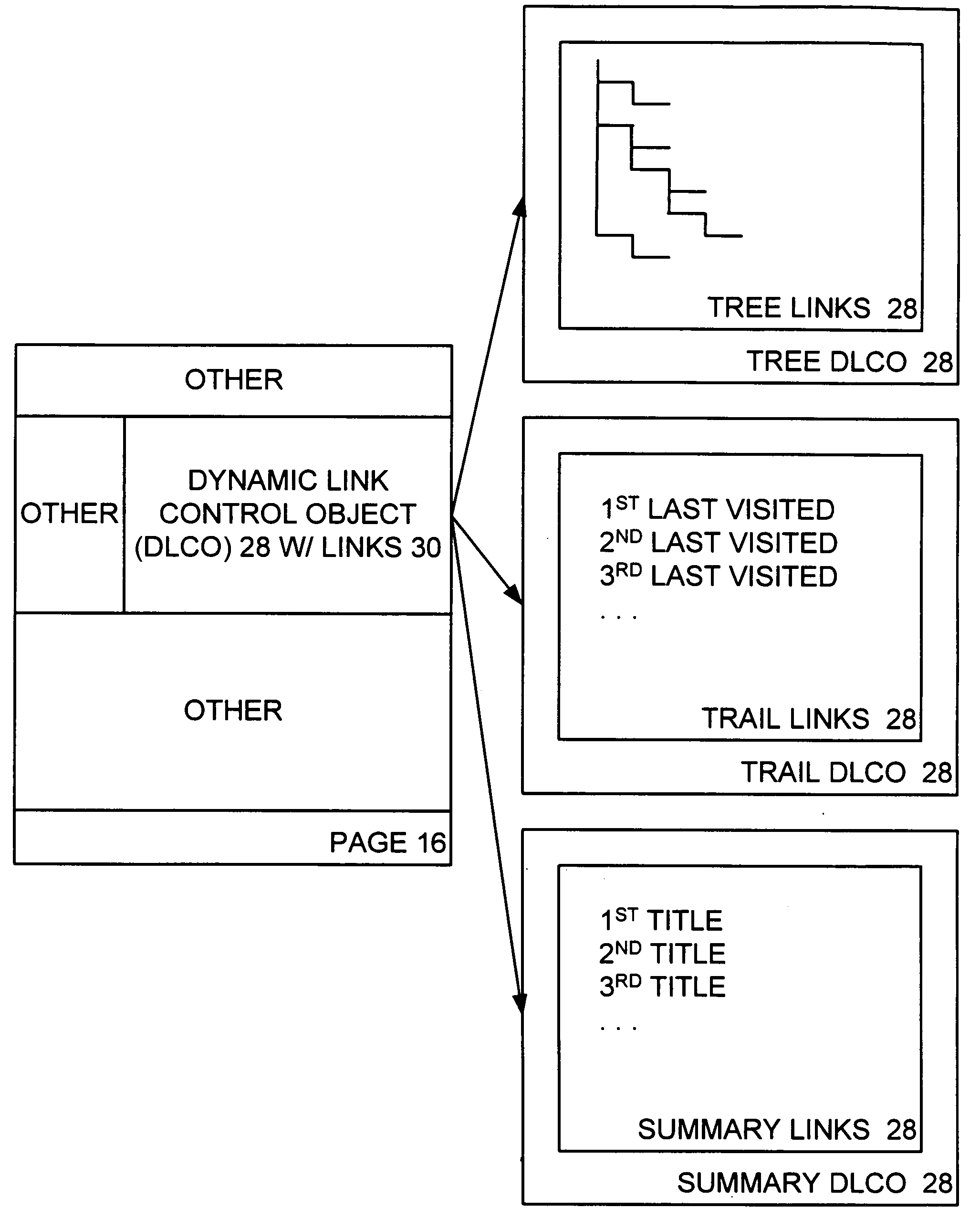
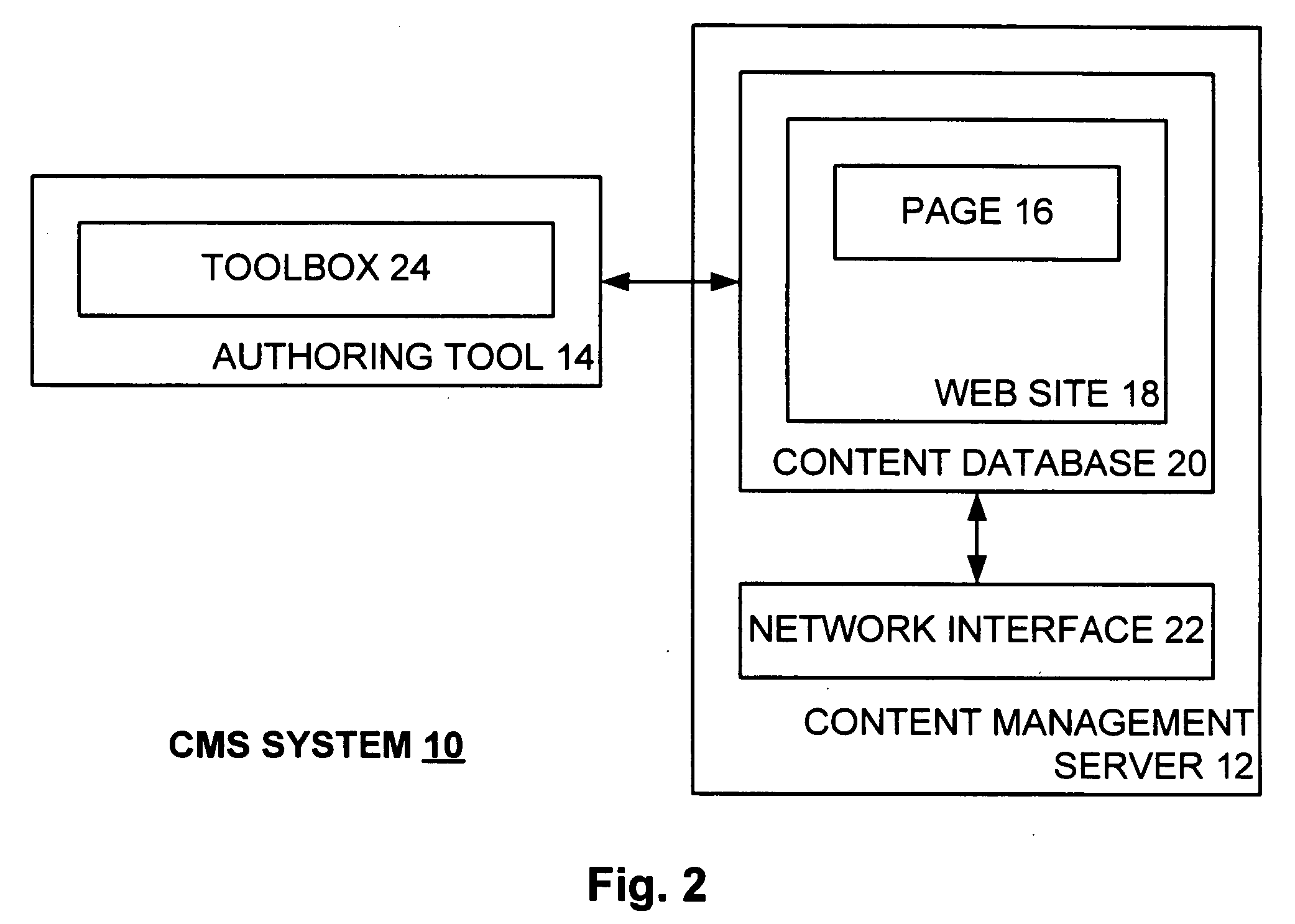
[0012] The aforementioned needs are satisfied at least in part by the present invention in which a dynamic link control object (DLCO) is positioned on a page of a web site. The web site is hosted by a content management server (CMS) that stores the page with the DLCO therein and serves same to a requester thereof. The page as served to the requestor has a context associated therewith. The DLCO on the page as viewed by the requestor displays navigation links associated with the page, where the displayed navigation links dynamically vary according to the context of the page. Thus, the DLCO on a first page with a first context may display different links as compared to the DLCO on a second page with a second context. A designer designing a page creates particular types of links on such page by placing the DLCO on the page without specifically defining each link.

Problems solved by technology

Thus, the designed designing the page had to possess a considerable amount of knowledge regarding the use and operation of the specialized authoring tool, full mastery of which could take a considerable amount of time.
As a result, a typical non-technical enterprise functionary could not easily edit a designed page, such as for example to modify the page or to create a similar page, without the aid of the designer.
Moreover, such functionary could not easily create and design such a page without the aid of such designer.

Method used


Image

  • Dynamic link control object for dynamically presenting link options in connection with a content management server system
  • Dynamic link control object for dynamically presenting link options in connection with a content management server system
  • Dynamic link control object for dynamically presenting link options in connection with a content management server system

Examples


Embodiment Construction

Computer Environment

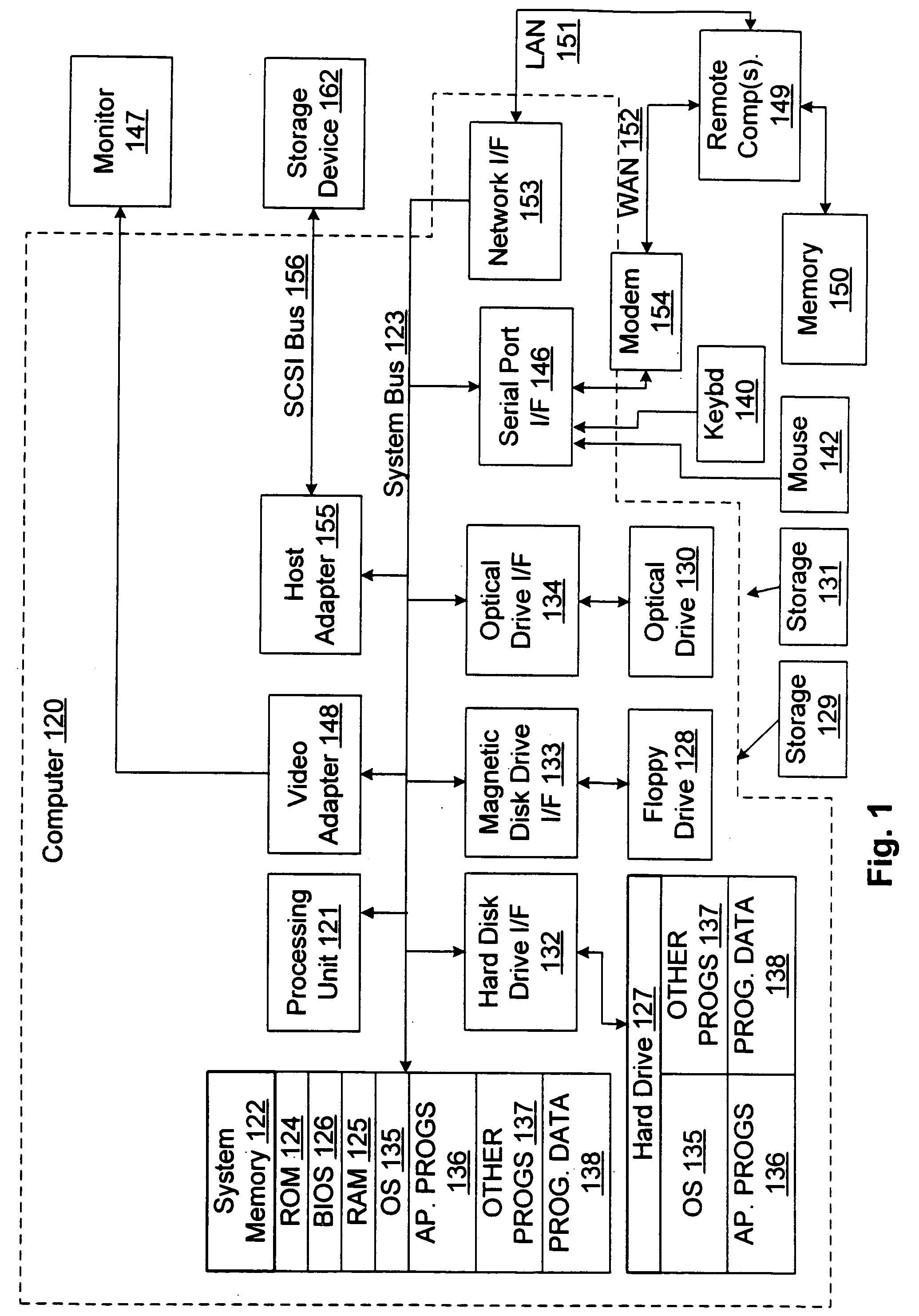
[0021]FIG. 1 and the following discussion are intended to provide a brief general description of a suitable computing environment in which the present invention and / or portions thereof may be implemented. Although not required, the invention is described in the general context of computer-executable instructions, such as program modules, being executed by a computer, such as a client workstation or a server. Generally, program modules include routines, programs, objects, components, data structures and the like that perform particular tasks or implement particular abstract data types. Moreover, it should be appreciated that the invention and / or portions thereof may be practiced with other computer system configurations, including hand-held devices, multi-processor systems, microprocessor-based or programmable consumer electronics, network PCs, minicomputers, mainframe computers and the like. The invention may also be practiced in distributed computing environme...


PUM


Abstract

A dynamic link control object (DLCO) is positioned on a page of a web site. The web site is hosted by a content management server (CMS) that stores the page with the DLCO therein and serves same to a requestor thereof. The page as served to the requestor has a context associated therewith. The DLCO on the page as viewed by the requester displays navigation links associated with the page, where the displayed navigation links dynamically vary according to the context of the page. Thus, the DLCO on a first page with a first context may display different links as compared to the DLCO on a second page with a second context. A designer designing a page creates particular types of links on such page by placing the DLCO on the page without specifically defining each link.

Description

CROSS-REFERENCE TO RELATED APPLICATION [0001] The present application is related to U.S. patent application Ser. No. ______, filed concurrently herewith under Attorney Docket No. MSFT-1947 and entitled “PLACEHOLDER CONTROL OBJECT FOR CREATING AND VIEWING CONTENT IN CONNECTION WITH A CONTENT MANAGEMENT SERVER SYSTEM”, hereby incorporated by reference in its entirety.TECHNICAL FIELD [0002] The present invention relates to a content management serer system with a placeholder control object that functions in an authoring mode to facilitate authoring of content on a page and in a presentation mode to facilitate presentation of the authored content on the page. More specifically, the present invention relates to such a placeholder control object that is served with the page and that assumes the proper mode depending on whether the page is being authored or presented. BACKGROUND OF THE INVENTION [0003] As may be appreciated, a content management server (CMS) is employed by an enterprise or...

Claims


Application Information

Patent Timeline
Patent Type & Authority Applications(United States)
IPC IPC(8): G06F12/00G06F17/30
CPCG06F17/30882G06F17/30873G06F16/9558G06F16/954
Inventor KARATAL, BURHAN KEREMCAWOOD, STEPHEN GRANTKUMARAVEL, ARUL
Owner MICROSOFT TECH LICENSING LLC
Why Eureka
Try Eureka