
Enhanced performance torroidal coolant-collection manifold
a technology of torroidal coolant and manifold, which is applied in the direction of machines/engines, gas turbine plants, hot gas positive displacement engine plants, etc., can solve the problems of significant non-uniform flow in the coolant tube or passage, so as to reduce the pressure loss in the manifold
- Summary
- Abstract
- Description
- Claims
- Application Information
AI Technical Summary
Benefits of technology
Problems solved by technology
Method used
Image

Examples
Embodiment Construction
(s)
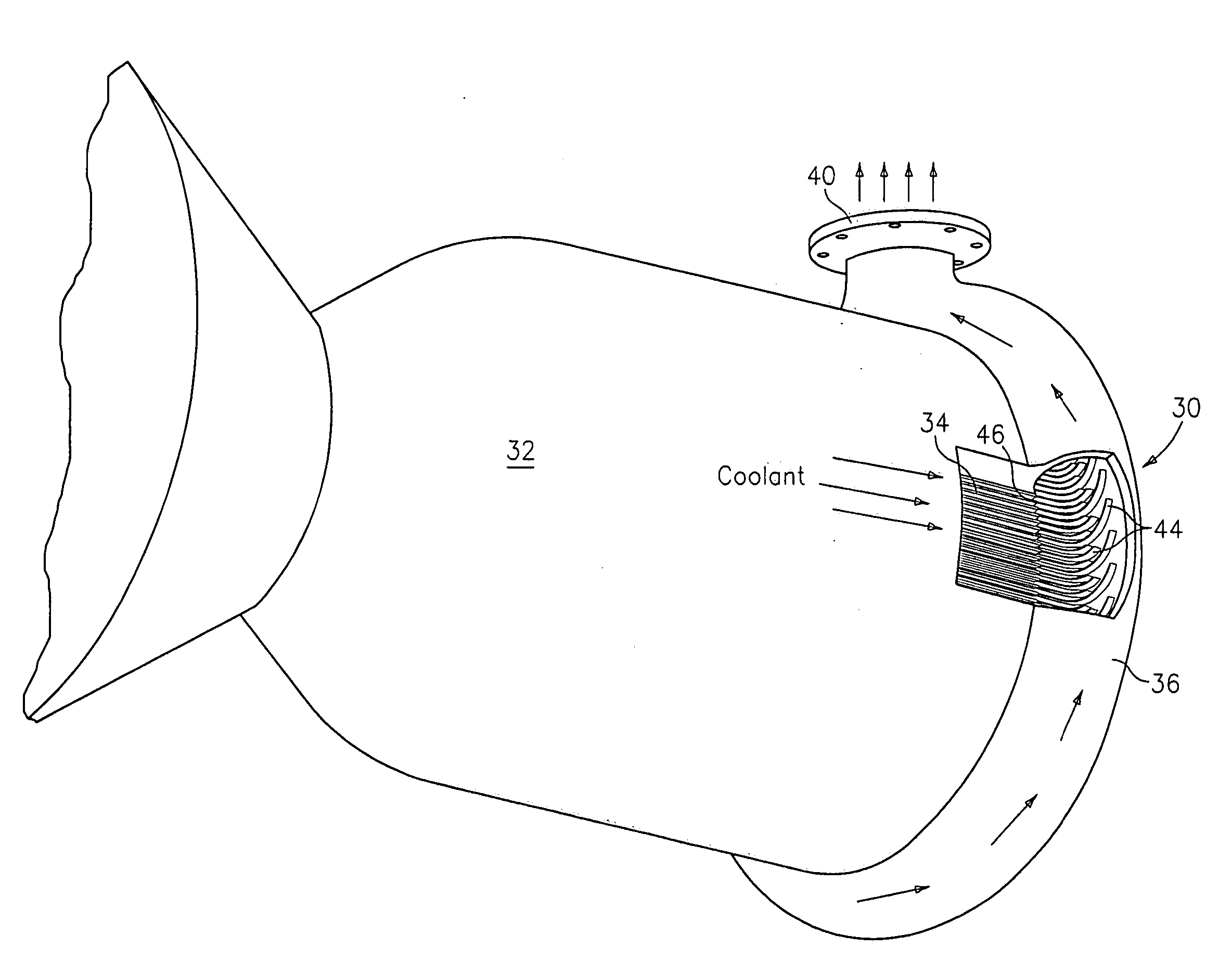
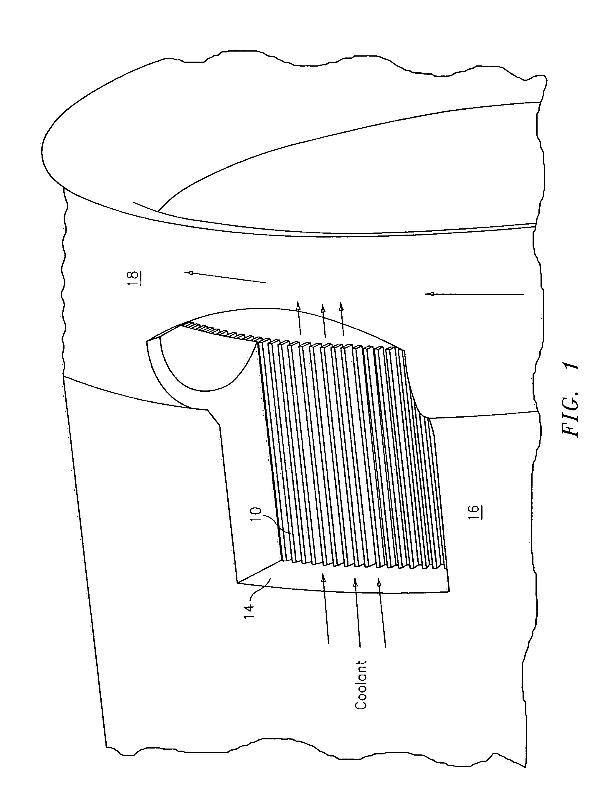
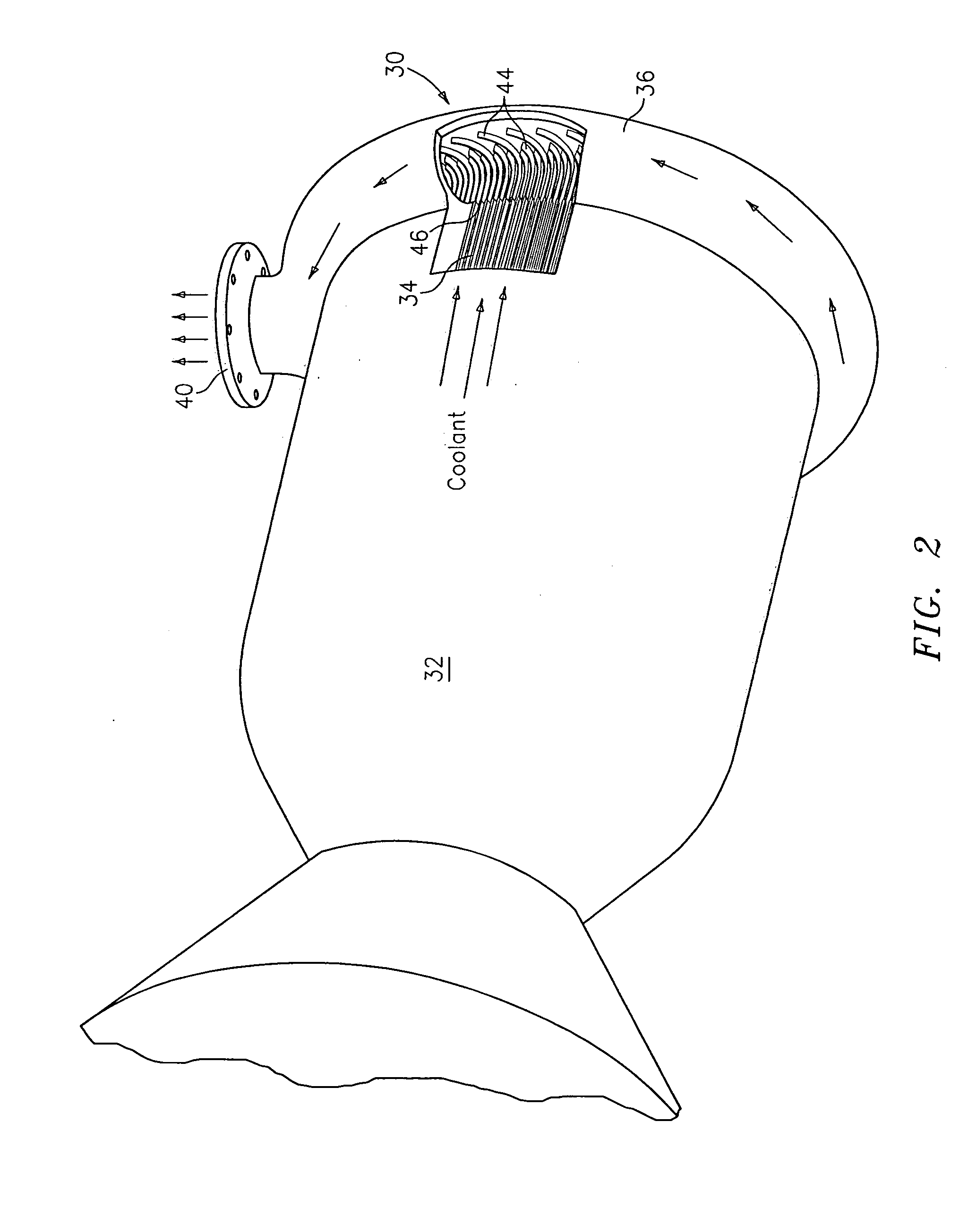
[0013] Referring now to FIGS. 2 and 3, an improved system 30 for cooling a combustion chamber 32 of an engine, such as a rocket engine, is provided. The system 32 has a plurality of tubes or passages 34 which form the cylindrical wall of the combustion chamber 32. The coolant tubes or passages 34 are used to transport a cooling fluid from a source (not shown) of the fluid to a torroidal coolant-collection manifold 36.
[0014] The torroidal coolant-collection manifold 36 is located adjacent an end 38 of each coolant tube or passage 34. The torroidal coolant-collection manifold 36 has a discharge port 40. While ordinarily the manifold 36 has a single discharge port 40, it may have a plurality of such ports if desired.
[0015] As can be seen from FIGS. 2 and 3, a plurality of vanes 44 are provided within the manifold 36. Each vane 44 is aligned with a respective coolant tube or passage 34 and is located adjacent an opening 46 in said respective coolant tube or passage 34. Each vane 44...
PUM
 Abstract
Description
Claims
Application Information