Fitting for a vehicle seat

a vehicle seat and seat technology, applied in the field of vehicle seat fitting, can solve the problem of high load in the fitting, and achieve the effect of reducing the peak load

Inactive Publication Date: 2005-08-18
KEIPER SEATING MECHANISMS CO LTD
View PDF15 Cites 34 Cited by
  • Summary
  • Abstract
  • Description
  • Claims
  • Application Information

AI Technical Summary

Benefits of technology

[0004] One aspect of the present invention is based on the object of improving a fitting of the type mentioned above, in particular reducing the peak loads. In accordance with this aspect, a fitting for a vehicle seat, in particular for a motor vehicle seat, has a first fitting part, a second fitting part connected by a gear mechanism to the first fitting part, a driving ring, which at least partially defines an eccentric and is mounted rotatably in the first fitting part, for driving a rolling movement of the second fitting part on the first fitting part, and a rotatably mounted, drivable driving bushing for rotating the driving ring, wherein the driving bushing and the driving ring are connected to each other in a form-fitting manner by a transmission profile.
[0005] The fact that the driving bushing and the driving ring are connected to each other in a form-fitting manner by a transmission profile means that relatively high loads can be transmitted via this connection. This improves the possibility of using the fitting as a motor-adjustable fitting and reduces the peak load on the individual components. The fitting is designed in such a manner that it is more efficient under load than without a load. In the case of two fittings according to the invention having a common drive shaft, reliable synchronization is possible when the drive shaft is installed.
[0006] In addition, the form-fitting transmission profile of the driving bushing and driving ring, on the one hand, and the eccentric, on the other hand, is preferably arranged in the same plane, thus enabling a higher driving torque to be transmitted by avoiding multiaxial stress states. This also improves the possibility of using the fitting as a motor-adjustable fitting. Because of the improved load transmission with the form-fitting engagement between the driving bushing and driving ring, a preferred formation of the driving bushing from plastic is possible, which permits more complex geometries and reduces the production costs.
[0009] Because an elastic element, which is effective in the radial direction, is provided in the region of the sliding bearing, it is possible for torque peaks, which occur during no-load operation when passing through narrow points, to be reduced, with the result that the peak load on the individual components is reduced. In this case, the self-locking condition of the fitting, the controlling behavior of the wedges and the play-free setting are not changed, and, on the contrary, the service life is extended in terms of wear. The elastic element may additionally also act as a damping element.
[0010] The elastic element, which is preferably provided with an annular basic shape, is preferably arranged at a point where there is no relative movement during the adjustment of the fitting, for example directly between the sliding bearing and the second fitting part, or, in order to simplify the installation, between a bushing or a receptacle, on the one hand, and the sliding bearing, on the other hand. A design made of plastic affords the advantages of simple production and specific adjustability of the properties. The elastic element may also be formed from spring steel sheet and may, for example, have a corrugated shape in the circumferential direction. The receptacle or the spring steel sheet can transform into a block in the event of a crash, i.e. the effect of the elastic element can be neutralized.

Problems solved by technology

When the fitting is adjusted by motor, there is, however, the problem that undesirable, high loads occur in the fitting, particularly when approaching the end stop.

Method used


Image

  • Fitting for a vehicle seat
  • Fitting for a vehicle seat
  • Fitting for a vehicle seat

Examples


first modified embodiment

[0045] In a first modified embodiment, in order to simplify the installation, the sliding bearing bushing 128 together with the elastic element 146 are prefitted within a bushing 148 made of steel, or the elastic element 146 is injected between the sliding bearing bushing 128 and the bushing 148, and then this subassembly is pressed into the second fitting part 112.

second modified embodiment

[0046] In a second modified embodiment, this bushing is designed as a receptacle 148′ with the elastic element 146′ inserted between its edge regions, which are bent at right angles, and fitted on the sliding bearing bushing 128, it also being possible here for the elastic element 146′ to be injected between the sliding bearing bushing 128 and receptacle 148′. As in the case of the first modification, this prefitted subassembly is pressed into the second fitting part 112. In the event of a crash, the edge regions of the receptacle 148′ are pressed together with the sliding bearing bushing 128 to form a block, with the result that the effect of the elastic element 146′ is neutralized.

third modified embodiment

[0047] In a third modified embodiment, the elastic element 146″ consists of steel spring sheet with an annular basic shape and has, along its circumference, a corrugated shape which can be used to absorb the radially effective forces. In the event of a crash, this steel spring sheet is also pressed in a block, i.e. the elasticity is likewise removed.

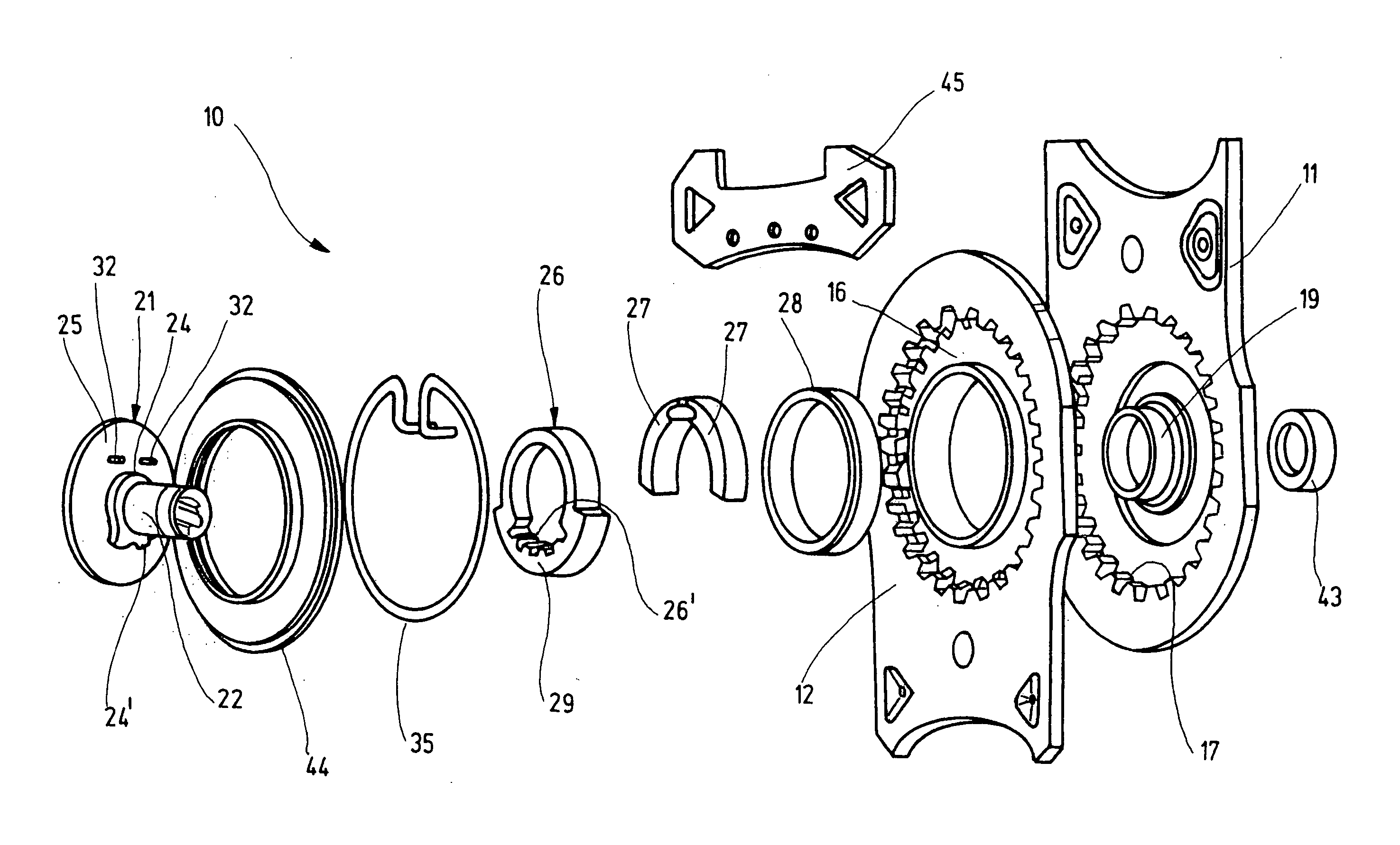
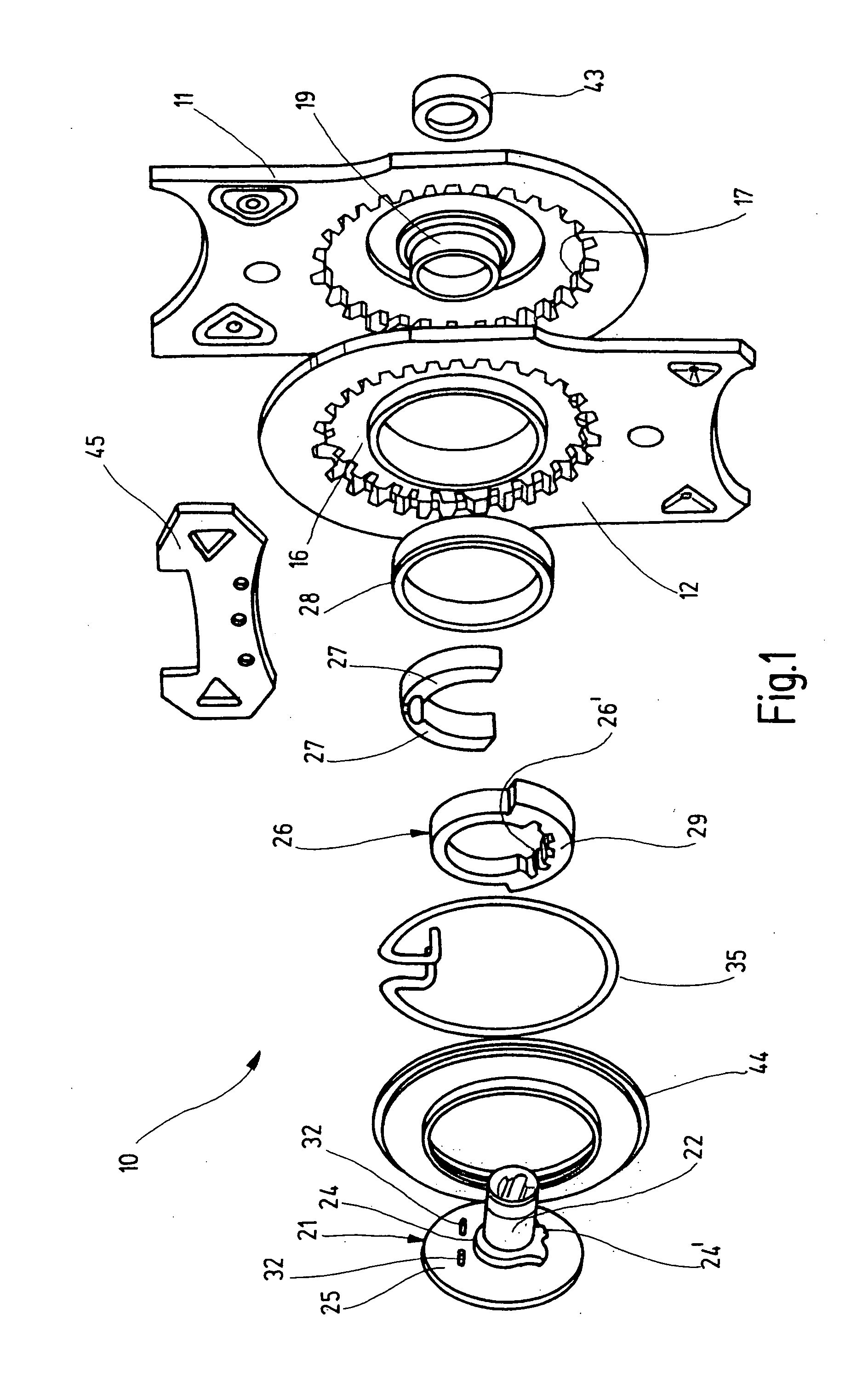
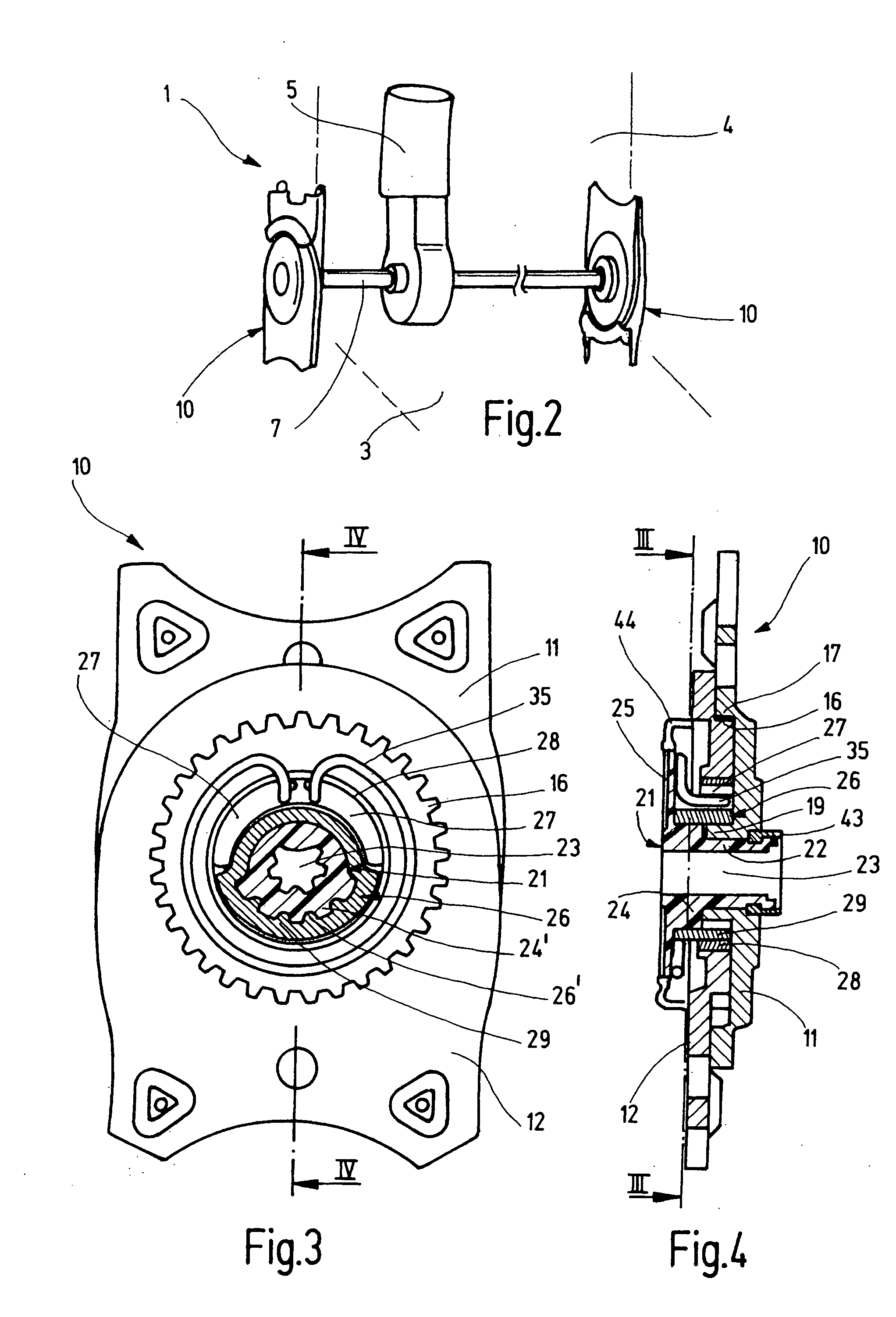
[0048] The third exemplary embodiment largely corresponds to the second exemplary embodiment, for which reason components which are identical and act in an identical manner bear reference numbers incremented by 100. Instead of the eccentric composed of a driving ring and wedge segments, the fitting 210 has a single-piece substantially rigid eccentric 226 which is rotated by the driving bushing 221, which is mounted in the first fitting part 211, and rotates in the sliding bearing bushing 228. The sliding bearing bushing 228 is mounted in turn in the second fitting part 212 with the interposition of an elastic element 246. The damping ele...


PUM


Abstract

In the case of a fitting for a vehicle seat, in particular for a motor vehicle seat, having a first fitting part (11), a second fitting part (12) connected by a gear mechanism to the first fitting part (11), a driving ring (26), which at least partially defines an eccentric (27, 29) and is mounted rotatably in the first fitting part, for driving a rolling movement of the second fitting part (12) on the first fitting part (11), and a drivable driving bushing (21) which is mounted rotatably, the driving bushing (21) and the driving ring (26) are connected to each other in a form-fitting manner by a transmission profile (24′, 26′).

Description

CROSS-REFERENCE TO RELATED APPLICATION [0001] This is a continuation of PCT / EP02 / 09534, which was filed Aug. 27, 2002, and is entirely incorporated herein by reference.BACKGROUND OF THE INVENTION [0002] The present invention relates to a fitting for a vehicle seat, in particular for a motor vehicle seat, having a first fitting part, a second fitting part connected by a gear mechanism to the first fitting part, a driving ring, which at least partially defines an eccentric and is mounted rotatably in the first fitting part, for driving a rolling movement of the second fitting part on the first fitting part, and a rotatably mounted, drivable driving bushing for rotating the driving ring. [0003] DE 199 38 666 A1 discloses a fitting of this type, in which the driver necessary for the drive is of two-part design in the form of a driving bushing and a driving ring, in order to reduce a functionally induced backlash during reversal of direction. The driving bushing and driving ring are conn...

Claims


Application Information

Patent Timeline
Patent Type & Authority Applications(United States)
IPC IPC(8): A47C1/024B60N2/22B60N2/225
CPCB60N2/2254B60N2/2252
Inventor FINNER, HOLGERVEDDER, ANDREASSCHOLZ, GRITBUSCH, HEINRICHLEHMANN, ULRICH
Owner KEIPER SEATING MECHANISMS CO LTD
Why Eureka
Try Eureka