Apparatus and method for dispensing and folding of sheets from a stack

a technology of dispensing apparatus and stack, which is applied in the direction of coin-freed apparatus, pile separation, instruments, etc., can solve the problems of inability of a member of the public to grab a substantial part of the stack, and achieve the effects of preventing possible jamming of the dispensing mechanism, high friction, and large distan

Inactive Publication Date: 2014-03-04
INFOSTOP
View PDF23 Cites 10 Cited by
  • Summary
  • Abstract
  • Description
  • Claims
  • Application Information

AI Technical Summary

Benefits of technology

[0014]In an embodiment according to the present invention, the counter-rotatable rollers comprise an elastic material close to the surface thereof. A suitable choice of such a material prevents possible jamming of the removing mechanism if the surface of the roller is somewhat uneven or if the sheet for feeding through is slightly too thick for the distance between the rollers. This measure is also helpful in the throughfeed of possibly multiple sheets of paper in the event these stick together. The removing mechanism hereby becomes robust enough to prevent malfunction.
[0015]In a further embodiment the strip with the high friction has a slightly raised surface relative to the rest of the surface of the roller. It hereby becomes possible to realize a relatively large distance between the rollers, while the engagement by the strip with the high friction is maintained. The strip can further be somewhat yielding compared to the rest of the roller, for instance in order to prevent the above stated paper jam.
[0016]The high-friction strip is preferably fixed in the roller. A rather robust embodiment of the high-friction strip is hereby realized. This is for instance practical when a strip of material is used which has good frictional properties but which is not very strong in thin layers. It is possible here to envisage a thickness of the strip of several millimeters to several centimeters. Alternatively, the strip with high friction is arranged on the surface of the roller. It is possible here to envisage a strip which is adhered to the surface of an otherwise flat roller. This is for instance practical in an embodiment wherein the roller comprises a metal surface. A further advantage of a roller with a metal surface is that manufacturing techniques therefor enable a very high surface precision in the manufacture thereof. The strip with high friction is further preferably provided with resistance means such as teeth, ridges, needles and / or studs, and can optionally be arranged in freely movable manner in the immediate vicinity of or against the surface of at least one of the rollers. Just as a natural rubber or plastic surface, such means can provide resistance to a sheet of paper to be entrained. Such an embodiment has the advantage that the strip with the high friction can be moved to or held away from the point of engagement independently of the rotation of the rollers. Disruptions in the mechanism can hereby be prevented or solved in simple manner, for instance by causing sheets situated between the rollers to rotate and feeding them through, while the strip is held for instance on the underside of the roller during this process.
[0017]In a further preferred embodiment the removing mechanism comprises a lifting member for varying the height position of the stack of sheets close to the rollers during one or more stages of rotation of the rollers. This embodiment for the means for causing an engagement between at least one of the rollers and the bottom sheet of the stack by means of frictional force during one or more stages of rotation of the rollers has the advantage that rollers can be applied whose whole surface, or a large part of the surface, has a high friction. Lifting the stack of sheets during one or more stages of rotation of the rollers prevents a subsequent sheet being pulled along as soon as the bottom sheet has been advanced so far by the throughfeed that the sheet situated thereabove comes into contact with the rollers. The second sheet is therefore prevented from being entrained prematurely, and the effect is achieved that the sheets are dispensed independently of each other. The lifting member preferably comprises two lifting supports on either side of the rollers. It hereby becomes possible to ensure the desired contact with the rollers in simple and precise manner. The lifting supports are preferably placed at an angle relative to the stack of sheets. A more lateral movement and force can hereby be exerted on this stack still to be dispensed, whereby sagging of the sheets between the rollers is prevented. Engaging means are preferably provided to further prevent this sagging of the sheets. These engaging means consist of a shaft which is driven simultaneously with the lifting supports and to which pins or strips are fixed which pull the stack of sheets outward. In an alternative embodiment, the engaging means are embodied as rollers which are optionally provided with friction means.
[0018]A cam is preferably arranged on an outer end of at least one of the rollers for the purpose of actuating the lifting member. In relatively simple manner an accurate driving of the lifting member can hereby be realized, with predetermined lifting moments related to the position of the rollers.
[0019]The removing mechanism preferably further comprises means for placing the stack and the rollers under bias relative to each other. If the rollers are arranged on the top side of the stack, the stack is for instance pressed under bias against the rollers by means of a spring construction. An alternative here is that the rollers rest on the stack. It is possible here for the weight of the rollers to be at least partly compensated by a counterweight or a number of springs under bias. The mounting of the rollers preferably allows at least a play in the direction of the rollers relative to each other for the purpose of making it possible for the rollers to move apart relative to each other. It is possible here to envisage horizontally movable, biased rollers or for instance flexible shafts. Jamming of the apparatus in particular can hereby be prevented. In a further preferred embodiment, the transition between the coefficient of friction of a roller and the high-friction strip proceeds gradually in predetermined manner. It hereby becomes possible to cause the engagement of the sheet of paper to proceed gradually, whereby the peak load of engagement will be reduced.

Problems solved by technology

Due to a housing it is impossible for a member of the public to grab a substantial part of the stack.

Method used


Image

  • Apparatus and method for dispensing and folding of sheets from a stack
  • Apparatus and method for dispensing and folding of sheets from a stack
  • Apparatus and method for dispensing and folding of sheets from a stack

Examples


Embodiment Construction

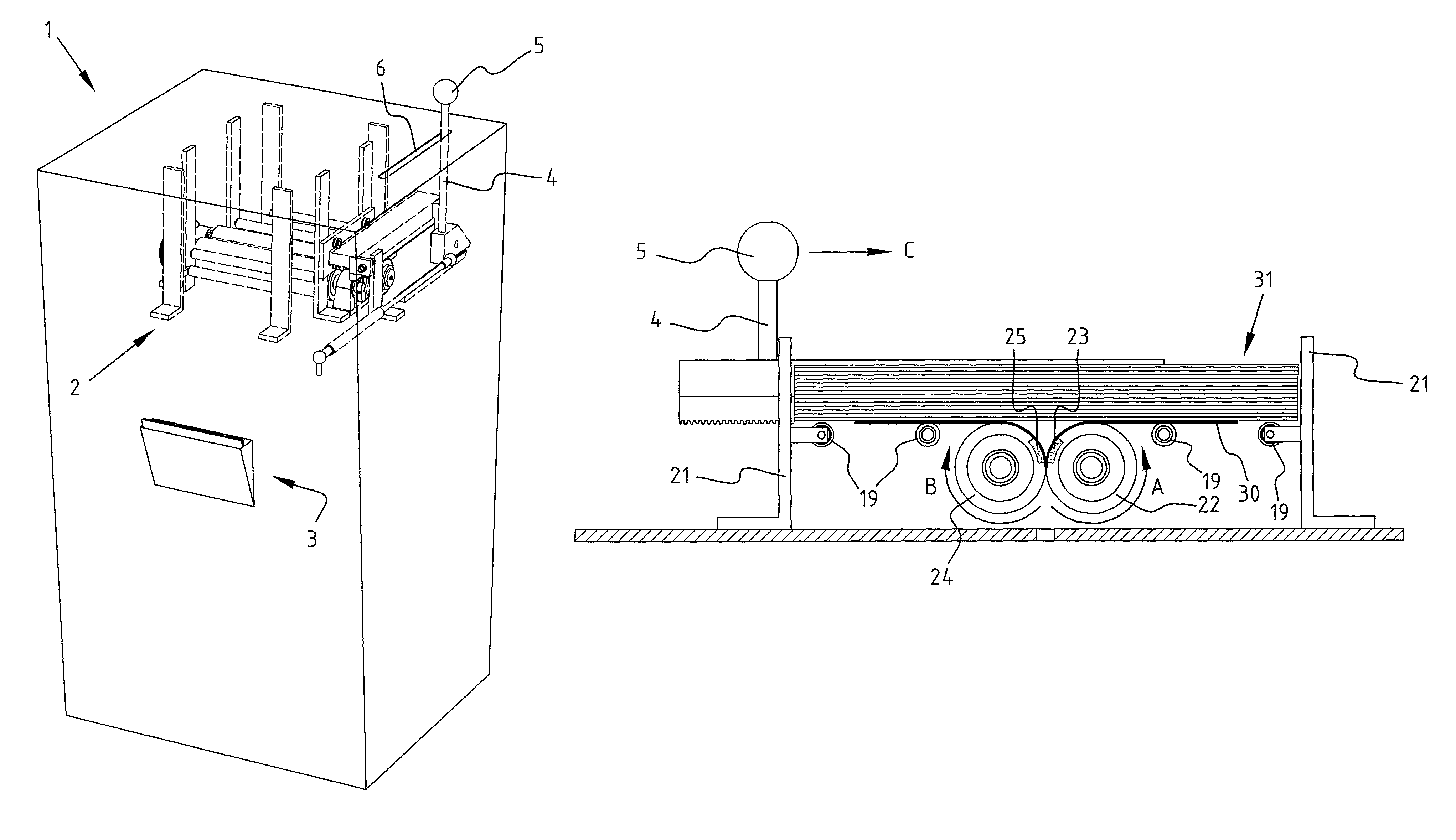
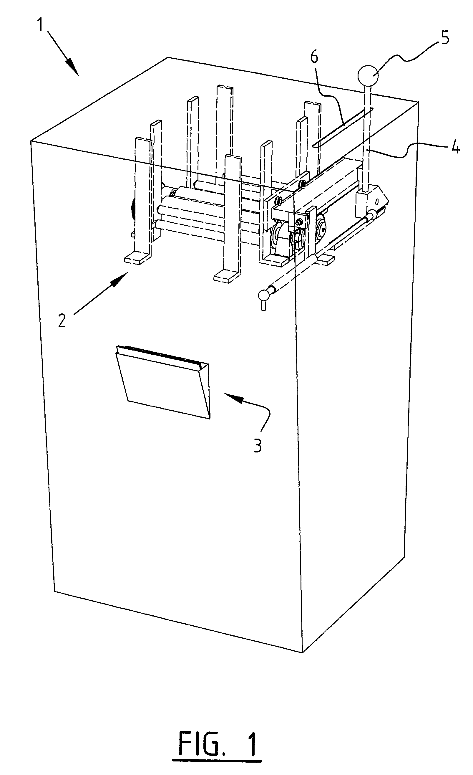
[0039]A first embodiment (FIG. 1) according to the present invention relates to a dispensing apparatus for sheets, such as for instance sheets having a size between B5 and A1. The apparatus is operated by means of a control knob 5 which is connected to rod 4, which rod 4 can move reciprocally through slot 6 on the top side of the apparatus. The sheets are ejected on the underside in a delivery bin 3. A removing mechanism 2 is shown with broken lines on the inside of dispensing apparatus 1.

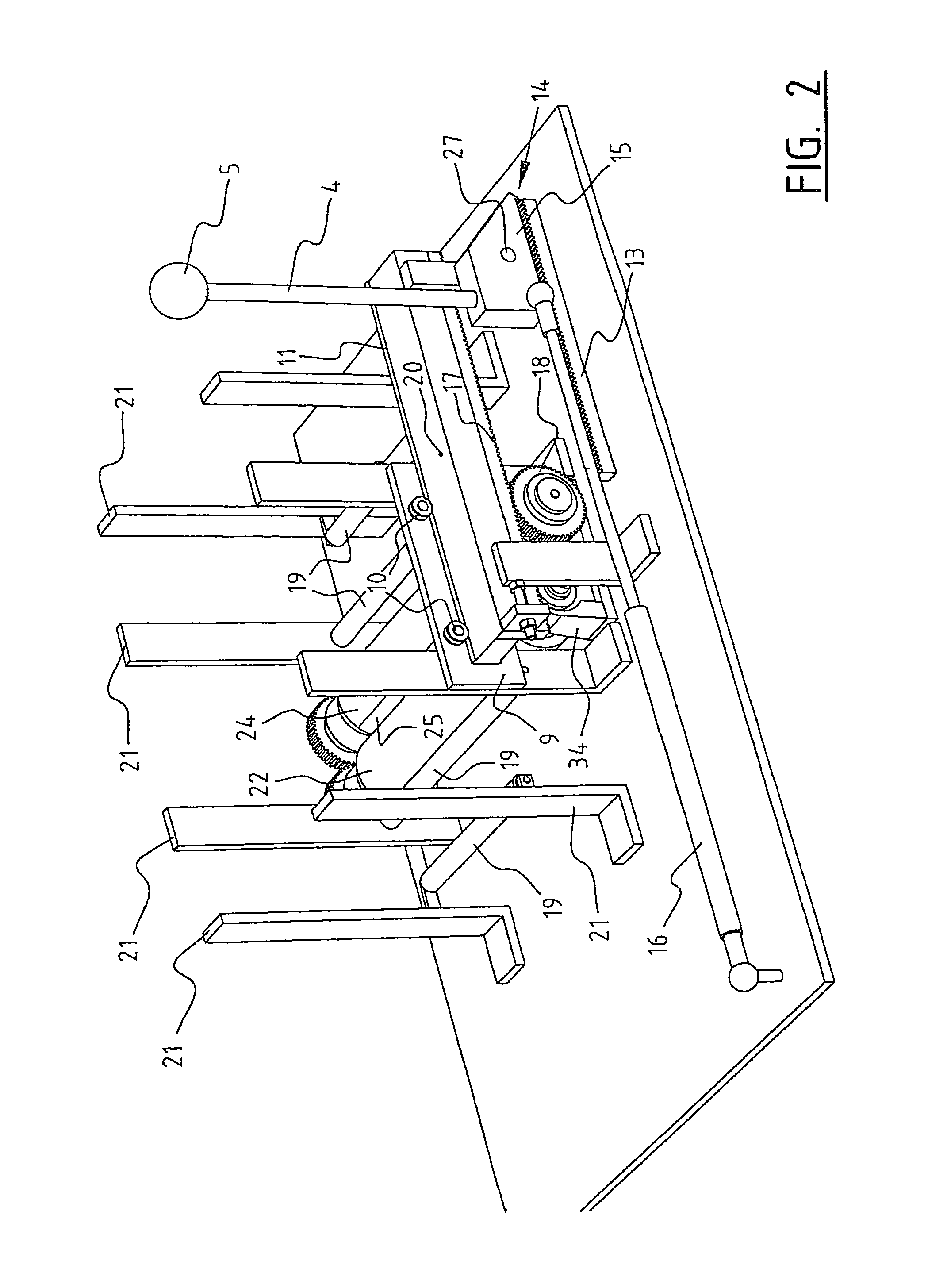
[0040]FIGS. 2 and 3 show an embodiment of the removing mechanism in greater detail. The removing mechanism is positioned on a baseplate 8. Fixed to this baseplate 8 are uprights 21, inside which uprights the surface area of a stack of sheets can be situated. Horizontal carriers 19 are fixed to the uprights. These carriers are preferably bearing mounted such that they can rotate freely about a central axis thereof. A stack of sheets can be placed on these supports 19. This stack of sheets further su...


PUM

PropertyMeasurementUnit
frictional forceaaaaaaaaaa
timeaaaaaaaaaa
mechanical drive forceaaaaaaaaaa

Abstract

A removing mechanism is disclosed for removing the bottom or top sheet from a stack of sheets; a delaying member for a delay of a predetermined time between the dispensing of two successive sheets; and an actuating mechanism for driving the removing mechanism, wherein the actuating mechanism is driven via a physically supplied mechanical drive force of an operator of the dispensing apparatus.

Description

BACKGROUND OF THE INVENTION[0001]1. Field of the Invention[0002]The present invention relates to a dispensing apparatus for sheets, a removing mechanism for removing a sheet from a stack of sheets, and to a method for dispensing sheets from a stack. It is often desired to distribute sheets such as maps sheets of paper, handouts, cards and the like to members of the public, without supervision, in a public space. Simply placing a box of sheets or a stack of sheets has the possible consequences that someone either takes a substantial part of or the whole stack or that the stack becomes soiled or is damaged, which causes have the result that the desired purpose is not achieved with the stack of sheets.[0003]2. Related Art[0004]It is therefore desirable for an apparatus to be provided for distributing the sheets among the public without the above-stated drawbacks occurring and wherein sheets can nevertheless be made available to the public in practical manner.SUMMARY OF THE INVENTION[00...

Claims


Application Information

Patent Timeline
Patent Type & Authority Patents(United States)
IPC IPC(8): G07F11/04B65H45/26A47K10/44
CPCB65H3/063B65H3/0669B65H2403/941B65H45/26B65H2513/50G07F11/045
Inventor LANGEN, JOHANNES CHRISTINALANGEN, HERMAN JOSEF
Owner INFOSTOP
Why Eureka
Try Eureka