Drive circuit for el display panel

a drive circuit and display panel technology, applied in static indicating devices, instruments, relays, etc., can solve the problems of difficult to implement a large high-resolution display panel of the former type, difficult control methods, relatively expensive,

Inactive Publication Date: 2005-08-18
TOSHIBA MATSUSHITA DISPLAY TECH
View PDF39 Cites 208 Cited by
  • Summary
  • Abstract
  • Description
  • Claims
  • Application Information

AI Technical Summary

Benefits of technology

[0010] To drive the pixel 16, a video signal which represents brightness information is first applied to the source signal line 18 with the gate signal line 17a selected. Then, the transistor 11a conducts, the storage capacitance 19 is charged or discharged, and gate potential of the transistor 11b matches the potential of the video signal. When the gate signal line 17a is deselected, the transistor 11a is turned off and the transistor 11b is cut off electrically from the source signal line 18. However, the gate potential of the transistor 11a is maintained stably by the storage capacitance (capacitor) 19. Current delivered to the EL element 15 via the transistor 11a depends on gate-source voltage Vgs of the transistor 11a and the EL element 15 continues to emit light at an intensity which corresponds to the amount of current supplied via the transistor 11a.

Problems solved by technology

It is difficult to implement a large high-resolution display panel of the former type although the former type is simple in structure and inexpensive.
The latter type allows a large high-resolution display panel to be implemented, but involves a problem that it is a technically difficult control method and is relatively expensive.
Since liquid crystal display panels are not self-luminous devices, there is a problem that they cannot display images without backlighting.
Also, there has been a problem that a certain thickness is required to provide a backlight, which makes the display panel thicker.
Therefore, there has been a problem of the lowered usability of light.
Also, there has been the problem of narrow color reproduction range.
However, since organic EL elements use current to emit light, there has been a problem that variations in the characteristics of the transistors will cause display irregularities.
This in turn causes variations in gradation output currents from output terminals, making it impossible to display images properly.

Method used


Image

  • Drive circuit for el display panel
  • Drive circuit for el display panel
  • Drive circuit for el display panel

Examples


Embodiment Construction

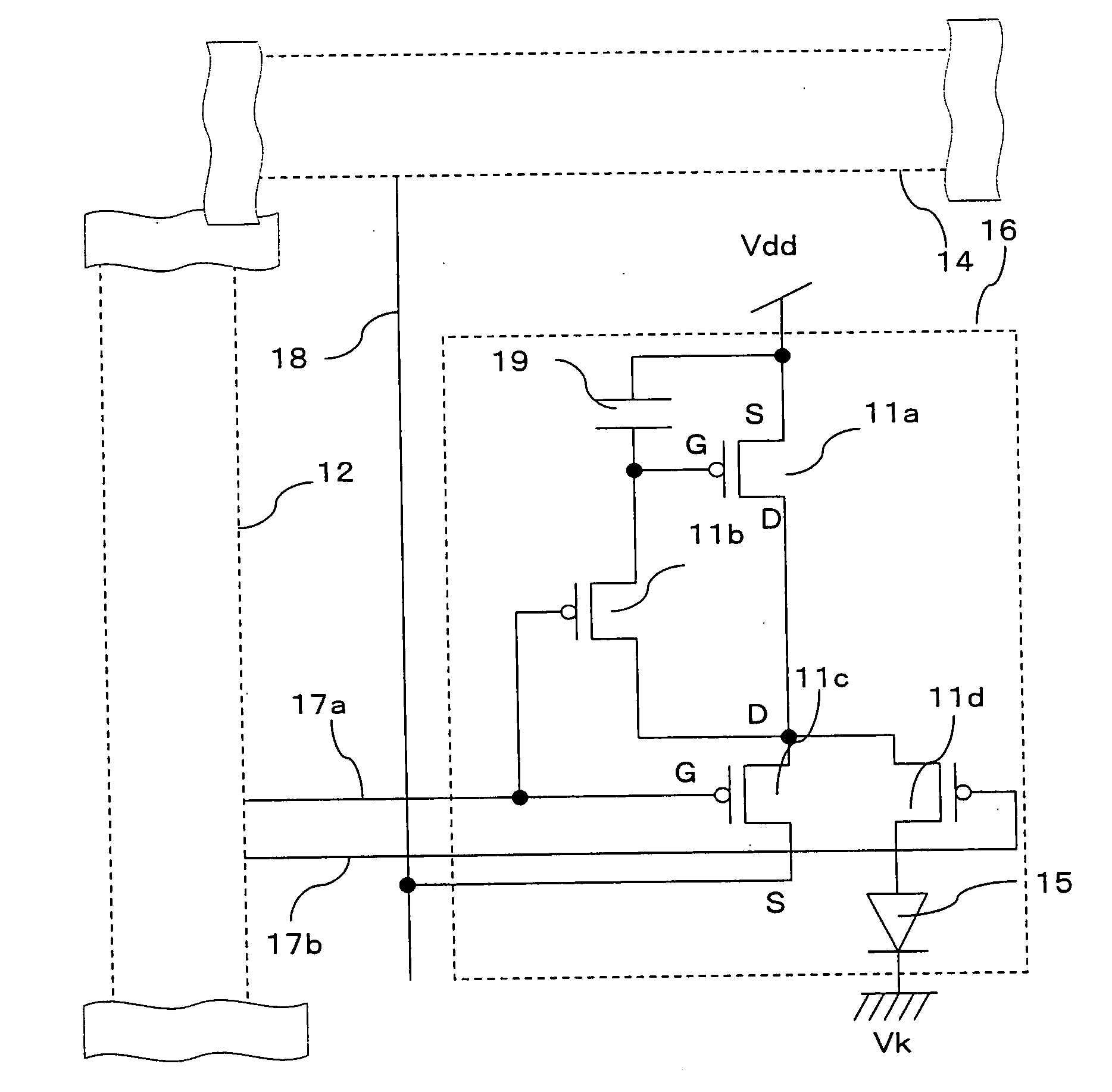
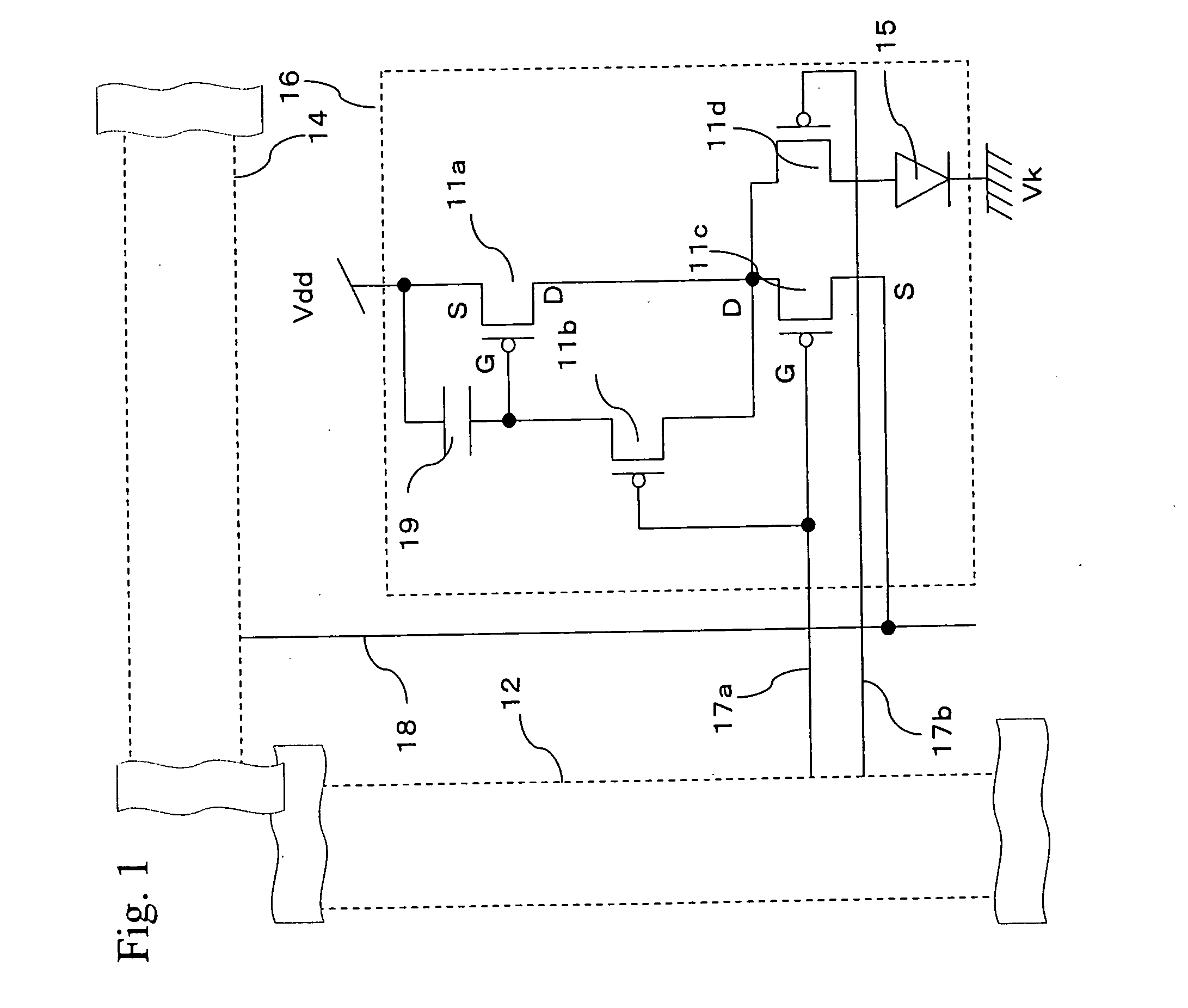
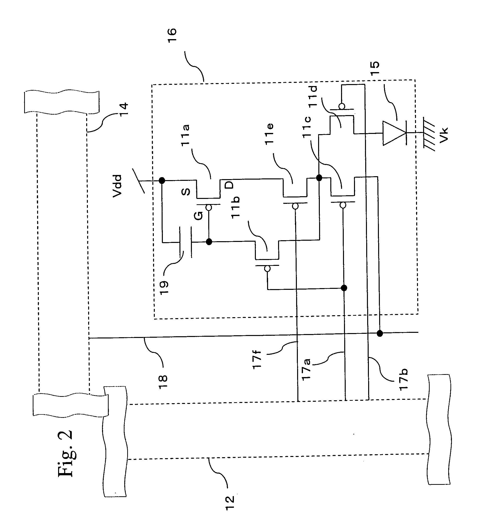
[0458] Some parts of drawings herein are omitted and / or enlarged / reduced herein for ease of understanding and / or illustration. For example, in a sectional view of a display panel shown in FIG. 11, a thin encapsulation film 111 and the like are shown as being fairly thick. On the other hand, in FIG. 10, a sealing lid 85 is shown as being thin. Some parts are omitted. For example, although the display panel according to the present invention requires a phase film such as a circular polarizing plate to prevent reflection, the phase film is omitted in drawings herein. This also applies to the drawings below. Besides, the same or similar forms, materials, functions, or operations are denoted by the same reference numbers or characters.

[0459] Incidentally, what is described with reference to drawings or the like can be combined with other examples or the like even if not noted specifically. For example, a touch panel or the like can be attached to a display panel in FIG. 8 to provide an ...


PUM


Abstract

To provide a source driver circuit for an EL display panel with reduced variations in output current. A source driver circuit contains unit transistors 634 each of which constitutes a single unit. The 0th bit consists of one unit transistor 634, the 1st bit consists of two unit transistors 634, the 2nd bit consists of four unit transistors 634, the 3rd bit consists of eight unit transistors 634, the 4th bit consists of 16 unit transistors 634, and the 5th bit consists of 32 unit transistors 634. Each unit transistor 634 composes a current mirror circuit in conjunction with a transistor 633a. Regulating the current Ib flowing through the transistor 633a allows for changing the current flowing through the unit transistors 634. Accurate source driver IC with small variations can be provided by configuring output current circuits with unit transistors and regulating reference currents so that the output current of the unit transistors can be regulated.

Description

TECHNICAL FIELD [0001] The present invention relates to a self-luminous display panel such as an EL display panel which employs organic or inorganic electroluminescent (EL) elements as well as to a drive circuit (IC) for the display panel. Also, it relates to an information display apparatus and the like which employ the EL display panel, a drive method for the EL display panel, and the drive circuit for the EL display panel. BACKGROUND ART [0002] Generally, active-matrix display apparatus display images by arranging a large number of pixels in a matrix and controlling the light intensity of each pixel according to a video signal. For example, if liquid crystals are used as an electrochemical substance, the transmittance of each pixel changes according to a voltage written into the pixel. With active-matrix display apparatus which employ an organic electroluminescent (EL) material as an electrochemical substance, emission brightness changes according to current written into pixels. ...

Claims


Application Information

Patent Timeline
Patent Type & Authority Applications(United States)
IPC IPC(8): G09G3/00G09G3/20G09G3/22G09G3/32H01L27/32H01L51/52
CPCG09G3/006G09G2320/08G09G3/2014G09G3/22G09G3/3241G09G3/325G09G3/3266G09G3/3283G09G2300/0408G09G2300/0417G09G2300/0452G09G2300/0809G09G2300/0842G09G2300/0861G09G2300/0866G09G2310/02G09G2310/0218G09G2310/0251G09G2310/0256G09G2310/0262G09G2310/027G09G2310/0283G09G2310/0297G09G2310/06G09G2310/061G09G2320/0214G09G2320/0223G09G2320/0233G09G2320/0261G09G2320/043G09G2320/0606G09G2320/0626G09G2320/066G09G2330/02G09G2330/12H01L27/3211H01L27/3213H01L27/3223H01L27/3244H01L51/5237H01L51/5262H01L51/5281H01L51/529H01L2251/568G09G3/20H10K59/351H10K59/88H10K59/353H10K59/12H10K59/131H10K50/846H10K50/85H10K50/87H10K50/844H10K50/86H10K71/861G09G3/30H05B33/14G09G3/32
Inventor TAKAHARA, HIROSHITSUGE, HITOSHI
Owner TOSHIBA MATSUSHITA DISPLAY TECH
Why Eureka
Try Eureka