High frequency partial boost power factor correction control circuit and method

a power factor and control circuit technology, applied in the direction of power conversion systems, instruments, climate sustainability, etc., can solve the problems of increasing the size of the circuit, not meeting the requirements of today's regulation requirements, and high costs

Active Publication Date: 2006-12-12
INFINEON TECH AMERICAS CORP
View PDF5 Cites 100 Cited by
  • Summary
  • Abstract
  • Description
  • Claims
  • Application Information

AI Technical Summary

Problems solved by technology

Because the inductor operates at the line frequency, the physical size and inductance size are normally very large, requiring high costs and increasing size of the circuit.
The input current waveform is smoothed, but typically does not meet today's regulation requirements.
Manufacturers use this method to smooth the input current which may satisfy some applicable regulation standards, in particular in Japan, but may not meet the strict IEC standard for the European markets.
Also the inductor operates at the line frequency and its physical size and inductance are still large, resulting in still high costs and circuit size.
However, even this circuit has drawbacks.
In particular, the high frequency PWM switching causes high switching losses, less efficiency and creates electromagnetic interference (EMI) noise and 100% PFC may be more than is necessary for many design applications.

Method used


Image

  • High frequency partial boost power factor correction control circuit and method
  • High frequency partial boost power factor correction control circuit and method
  • High frequency partial boost power factor correction control circuit and method

Examples


second embodiment

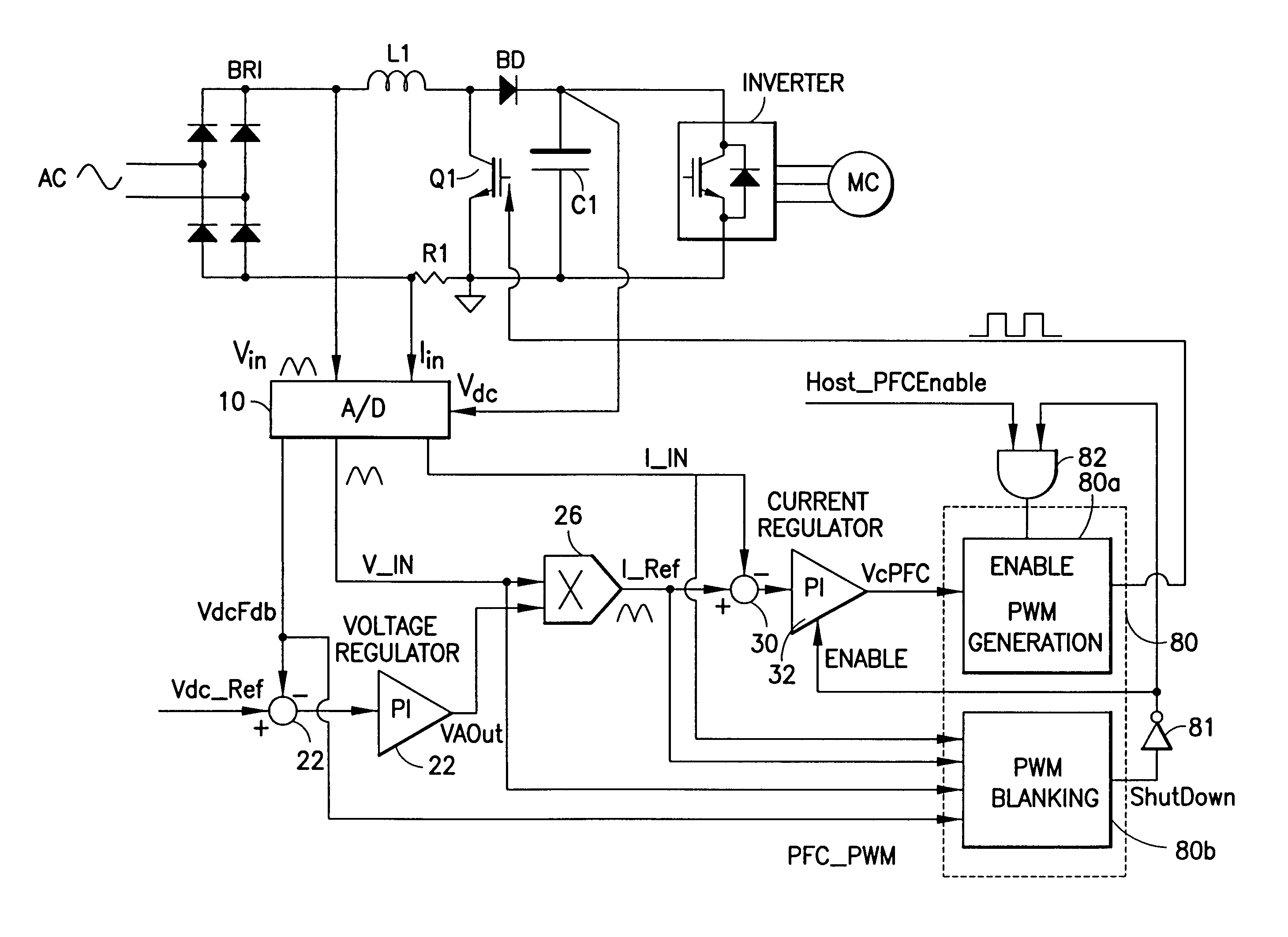
[0039]FIG. 8 illustrates a second embodiment of a high frequency partial PFC circuit according to an embodiment of the present application. The partial PFC circuit of FIG. 8 is very similar to that of FIG. 5, and operates in a similar manner. Common reference numbers and symbols are used for corresponding elements of FIG. 5 and FIG. 8. In FIG. 8, a PFC pulse width modulated device (PFC_PWM) 80 may be provided in place of partial PFC controller 40 and comparator 34. The PFC_PWM includes pulse width modulated (PWM) generator 80a that provides the pulse width modulated signal used to control switch Q1 and a pulse width modulate (PWM) blanking device 80b which provides a signal, ShutDown, to disable or blank the PWM generator 80a. The ShutDown signal may be an enable / disable signal that may be used to enable, or disable the PWM generator 80a.

[0040]The PWM Blanking device 80b takes as inputs the input current I_IN, the reference current I_Ref, the input voltage V_IN and the DC voltage V...

third embodiment

[0050]In another embodiment of the present application, it may be desireable to control the DC Bus voltage of the partial PFC circuit. In the partial PFC circuit of the present application, it is no longer necessary for the DC bus voltage to be set higher than the peak AC input voltage, rather the DC bus voltage should be set around the peak of the AC input voltage. In order to maintain continuous inductor current while the PWM signal is disabled, however, the instant DC voltage is preferably slightly lower than the instant AC voltage. How close the DC voltage is to the AC peak voltage will affect the current waveform quality as well as the power factor and the harmonic content of the circuit.

[0051]In the present embodiment, an objective is to provide a method and circuit to control the DC bus voltage, however, the objective is not necessarily to maintain a fixed DC voltage that is higher than the maximum peak AC voltage, but rather to regulate the DC bus voltage in order to generat...


PUM


Abstract

A circuit for providing power factor correction includes a boost converter circuit with a boost inductance and a power factor correction switch and a control circuit. The control circuit provides a pulse width modulated signal to control the on time of a PFC switch, and also includes a power factor correction pulse width modulated device receiving as inputs a rectified AC input voltage, a DC bus voltage, a signal proportional to the current through the inductor and a reference current signal. The power factor correction pulse width modulated device also includes a pulse width modulated generator operable to provide the pulse width modulated signal to control the on time of the PFC circuit and a pulse width modulated blanking device operable to provide an enable / disable signal to disable the pulse width modulated generator when predetermined conditions are met.

Description

CROSS-REFERENCE TO RELATED APPLICATIONS[0001]This application is a continuation in part of application Ser. No. 11 / 165,939 filed Jun. 24, 2005, entitled HIGH FREQUENCY PARTIAL BOOST POWER FACTOR CORRECTION CONTROL CIRCUIT AND METHOD which claims the benefit and priority of Provisional Application Ser. No. 60 / 583,752 filed Jun. 28, 2004, entitled A NEW HIGH-FREQUENCY PARTIAL BOOST POWER-FACTOR-CORRECTION CONTROL METHOD, the entire disclosure of which is hereby incorporated by reference herein. This application also claims benefit of and priority to Provisional Application Ser. No. 60 / 626,113 filed Nov. 8, 2004 entitled PWM BLANKING ALGORITHM IN HIGH FREQUENCY PARTIAL PFC and Provisional Application Ser. No. 60 / 626,112 filed Nov. 8, 2004 entitled DC BUS VOLTAGE CONTROL METHOD IN HIGH-FREQUENCY PARTIAL PFC, the entire disclosures of which are hereby incorporated by reference herein.BACKGROUND OF THE INVENTION[0002]The present invention relates to power factor correction circuits, that ...

Claims


Application Information

Patent Timeline
Patent Type & Authority Patents(United States)
IPC IPC(8): G05F1/56
CPCG05F1/70H02M1/4225Y02B70/126Y02B70/10
Inventor TAKAHASHI, TOSHIOLI, YONG
Owner INFINEON TECH AMERICAS CORP
Why Eureka
Try Eureka